
Hoffmanamps Boardmaker InstructionsPage - Board Page 0 - Board Page 1 - Board Page 2 - Board Page 3 - Board Page 4 - Board Page 5 - Board Page 6To follow along with these pages you should go here to the library page and print out the layout diagram for the 5F6A Bassman board. |
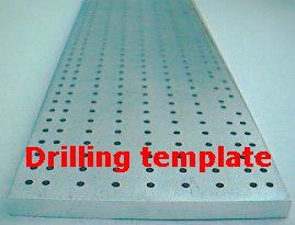 |
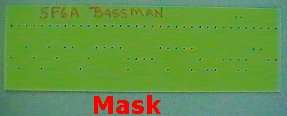
I will first define the items you will be using. A piece of 1/8" thick glass/epoxy circuit board material. The metal drilling template. This 1/4 inch thick metal item that has over 500 holes in it. This is the tool that makes it all possible. The drilling mask. The mask is a fiberglass template that only has the holes for the particular circuit board that you are building. The mask looks like a drilled circuit board with all the 3/32 holes, but it is only 1/16" thick. Two 3/32" metal alignment pins. (included with drilling template) Drill press. 3/32" drill bit. 3/16" drill bit. A clamping device like a vice grip or something similar. You could probably use tape if you were careful so that pieces do not move while drilling the two alignment holes. Lug tool. See this page. Lug press. See this page. Bent tip needle nose pliers. See the photo below. Wire cutters. Wire strippers. 24 gauge bare buss wire. Radio shack sells small spools of buss wire. 40 watt soldering iron. Radio shack 64-2071C 40W iron works great. .032 solder. Radio shack part number 64-009A works fine. 1 small and 1 large component lead bender. See this page. |
 |
|
Cut your piece of 1/8" thick circuit board a tiny bit longer than the finished length. I use a jigsaw with a fine tooth blade that is able to cut metal
like materials. The circuit board material is very hard and dense. Most likely you will not be able to cut the ends of the board perfectly square so cut your board a bit longer. Sand the ends of the board so that they are nice and square and to the proper length. I use a bench top sander that has a 9" round disk and a long 6" x 48" belt. I sand the ends of the board square on the 9" disk and I sand the long edges on the 6" x 48" belt. |
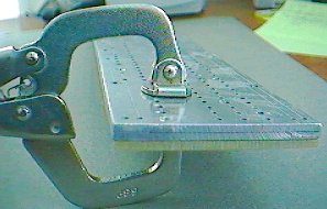 |
Clamp your blank piece of board to the rear of the drilling template. You will align and clamp the board in the upper left corner of the drilling template. You always use the left end of the drilling template as your starting point. |
 |
 |
While the board is clamped to the drilling template, drill a pilot hole at each end of your circuit board using a 3/32" drill bit. These two
holes that you drill are holes that you will be using to install lugs into so only drill a hole at each end of your board that are actually holes used in the circuit that you are
building. I always use the line of holes that are 20mm down from the top edge of the drilling template. This line of holes is always used on all my board kits so there is no danger of drilling a hole in the board that will not be used. The two pilot holes I always drill are the first lug at the left edge of the board and the first lug at the right edge of the board. After drilling the two pilot holes, unclamp the drilling template from your circuit board. Tip: The more you use your 3/32 drill bit, the smaller the outside diameter will get. Eventually the drill bit will not be useable because the drilled hole size will be too small. If the lugs will not go into the hole or are difficult to press into the hole, it's time for a new drill bit. |
| Left edge | Right edge |
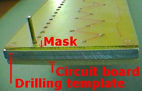 |
Put an alignment pin into each of the pilot holes that you drilled in your circuit board. You will have an alignment pin at each end of your circuit board. Slide the metal drilling template down onto the two alignment pins. Slide the fiberglass-drilling mask onto the two alignment pins. You should now have a stack with the blank circuit board on the bottom, the metal drilling template in the middle and the fiberglass-drilling mask on the top. You will be drilling only the holes that the mask has on its surface. That is why it is on top of the stack. There are over 500 holes in the drilling template but you only want to drill the holes on the mask. Mask tip: I use a red sharpie pen and connect all the dots on my mask so it is easy to see the holes that have to be drilled. |
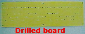 |
Drill all the holes that are on your mask using a 3/32" drill bit. Your drill bit will pass through a hole in the mask. Then it will pass through a hole in the metal drilling template. Then the drill bit will actually drill a hole in the fiberglass circuit board material. After you have drilled all the holes you can hold the whole assembly up to a light and look through to make sure that you haven’t missed drilling any holes. Disassemble the mask, drilling template and circuit board. |
| How to make a 4 power tube circuit board |
|
To make a 4 power tube version of any board you just add two more cathode/1 ohm bias checking resistors and two more screen grid resistors. To do this,
you drill all the holes in the mask starting from the left end and up to the cathode-screen grid resistor section and then stop. Do not drill past the last screen grid resistor,
you are going to stop and shift the mask to the right. Drill all the way to where the cathode resistors/1 ohms and screen grids are located. Then shift your drilling template to the right and drill another set of cathode/1 ohm-screen grid resistors. You can put all four cathode/1 ohms in a row and all four screen grids in a row or you can just double the pattern on the drilling mask. When you are done you will have 4 cathode/1 ohm resistor holes and 4 screen grid resistor holes. Now continue drilling all the holes to the right of the last screen grid resistor. |
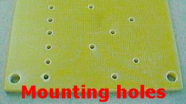 |
Drill the circuit board mounting holes using a 3/16" drill bit. The reason I use a 3/16" drill bit is because I use #8 screws to mount the circuit boards to the chassis. A 3/16" bit is about right for a #8 screw. I usually drill a hole in all four corners of the circuit board. If the circuit board is longer than 10 inches I will also drill two mounting holes in the middle of the board. In other words I will have 6 mounting holes in a long circuit board and 4 mounting holes in shorter circuit boards. I usually drill my mounting holes about 1/4" from the edges of the board. I drill the mounting holes by eye. You don’t use a template to drill the mounting holes. One reason for this is that your circuit board lengths and widths may vary a bit and the mounting holes might not end up where you want them. Now you should have all your holes drilled in your circuit board. |
|
Do any finish sanding that you may want to do. I usually do a quick wet sanding on all circuit board edges with a very fine grit emery cloth to give the edges
a nice clean edge. Wash your circuit board with soap and water to get rid of fingerprints, grease, oil, sanding dust, drilling dust and any other particles. Dry the circuit board with a cloth or paper towel. |
 |
|
Push all the turret lugs into the circuit board holes. Make sure you are putting the lugs in correctly with the board facing up. Double-check yourself,
if you install all the lugs on the wrong side of the board, the board will not be useable. I speak from experience, it has happened to me. Before you swage your lugs, make sure they are all pressed down flush with the surface of the circuit board. If you swage a lug that is not down flush on the board surface it will not be installed correctly. In other words, push all the lugs into the board as far as they will go. Swaging a lug is the process where the lug press flares out the rear of the lug so that it permanently attached to the circuit board. I have my lug press set up so that the tool with the hole is on top and the pointy tool is on the bottom. That way I can push all the lugs into all the holes on the circuit board and then I go over to the lug press and carefully swage all the lugs. Be careful not to knock any of the lugs out of their holes while handling the board. Now swage all your lugs on your lug press. Look at the back of the board after you are done to make sure that you swaged all the lugs. Your circuit board should now have all the lugs installed. This page has instructions on how to set up your lug press and how to swage the lugs. |
Enter My Tube Amp Parts Store Here
Mobile users Enter My Tube Amp Parts Store Here
The Tube amp Library of information
Click the link above for Tube amp info, Schematics, Board building information, Projects, Mods, Transformer diagrams, Photo's, Sound clips.
There are hundreds of pages of Tube amp information on my library page.
Please visit my Tube Amplifier Forum
Here's the place you can go to ask tube amplifier questions.
You will find a large community of friendly amp builders at the link above.
Check the huge library of Schematics here
Design your own custom Turret Board or Eyelet board
DIY Layout Creator file analyzer program
DIY Layout Creator file library
Sound clips and tunes of all types
How to email me
|
MEMBER OF PROJECT HONEY POT Spam Harvester Protection Network provided by Unspam |