
Hoffmanamps Boardmaker InstructionsPage - Board Page 0 - Board Page 1 - Board Page 2 - Board Page 3 - Board Page 4 - Board Page 5 - Board Page 6To follow along with these pages you should go here to the library page and print out the layout diagram for the 5F6A Bassman board. |
 |
|
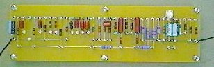
At this point you should have all your parts mounted to the circuit board. In the photo above you can see that all the parts are mounted and soldered. There
are some black wires and screws showing that will be explained further down this page. Now it's time to clean all the flux/resin spots off the board again. After soldering the parts onto the board you will have some new resin spots. I use my handy dental pick to flick off the spots after they have hardened up a bit then I use a soft bristled paint brush to sweep the board clean. |
 |
 |
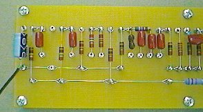
| Left end of board | Right end of board |
| I have split the complete board into two photos for better close ups. You can see a black wire on each end of the board. These wires are soldered to the two ground busses. The wires are black 18 gauge stranded wire. The left end ground buss goes to the pot harness and the right end goes to the transformer chassis ground. These two wires are explained in the board kit installation instructions which I have on line at this page. Schematics and info page | |
 |
 |
| Non reversed layout diagram | Layout diagram reversed |
 |
 |
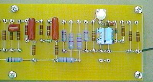
| Front of bias circuit board | Rear of bias circuit board |
|
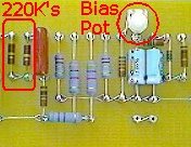
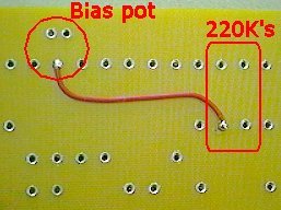
The top left diagram shows the bias circuit layout diagram area on the 5F6A board. The bottom left photo shows the bias circuit on the circuit board. The top right diagram is the same diagram only a reversed/mirror image. The bottom right photo is the back side of the bias circuit board. On the layout diagram there is a squiggly line that says "under Board". This is a wire that connects the bias circuit negative bias voltage to the two 220K power tube input grid resistors. It is connected from the bias pot over to the two 220K resistors. Notice the 220K resistors are joined by a small buss. The is where the bias wire is soldered. The negative bias voltage comes from the bias pot then enters the 220K's. When the board is installed in an amp, the bias voltage will then go to each power tube input grid. (pin#5). Some circuit boards have just one wire under the board like the 5F6A board in this example. Some circuit boards like the AB763 circuit have several wires under the board. Don't forget to connect the under board wires. Double check yourself to make sure you are connecting them properly. You are working on the back of the board and it is easy to get confused. |
|
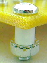 |
This is the mounting hardware that I use on most boards. It is a 5/8 inch #8 phillips head screw, a 1/4 inch nylon standoff and a #8 keps nut. On some boards like a Plexi circuit you may want longer standoffs. On most Marshall chassis the first pre amp power supply capacitor is under the circuit board. Usually this is a 50uf/50uf/500 volt capacitor. For mounting hardware I used a 3/4 inch hex threaded standoff, a 3/8 inch phillips head screw and a 1/2 inch phillips head screw. |
| Mounting hardware added |
| The circuit board is now finished. All of our parts have been mounted, all ground wires and under the board wires have been installed and all solder resin spots have been removed. |
Enter My Tube Amp Parts Store Here
Mobile users Enter My Tube Amp Parts Store Here
The Tube amp Library of information
Click the link above for Tube amp info, Schematics, Board building information, Projects, Mods, Transformer diagrams, Photo's, Sound clips.
There are hundreds of pages of Tube amp information on my library page.
Please visit my Tube Amplifier Forum
Here's the place you can go to ask tube amplifier questions.
You will find a large community of friendly amp builders at the link above.
Check the huge library of Schematics here
Design your own custom Turret Board or Eyelet board
DIY Layout Creator file analyzer program
DIY Layout Creator file library
Sound clips and tunes of all types
How to email me
|
MEMBER OF PROJECT HONEY POT Spam Harvester Protection Network provided by Unspam |