
Hoffmanamps Boardmaker InstructionsPage - Board Page 0 - Board Page 1 - Board Page 2 - Board Page 3 - Board Page 4 - Board Page 5 - Board Page 6To follow along with these pages you should go here to the library page and print out the layout diagram for the 5F6A Bassman board. |
 |
If you are installing the board kit into an amp yourself, you can assemble the pot harness in the amp itself. You do not have to make the pot harness on a jig.
If you are sending a board kit to a customer you should assemble the pot harness unless they want to do it themselves. In that case just give them all the raw parts in a bag and
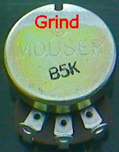
let them do it. Here are the instructions for making a pot harness assembly. Notice that I have ground the bottom edge of the pot clean so that I can solder a buss wire down the back of all the pots. The mouser pots have a gold finish that solder will
not stick to, so I grind a small spot clean where I want to solder. |
 |
| Here is the layout diagram for the 5F6A pot harness. The small numbers indicate where a pot wire is attached on the circuit board. |
 |
|
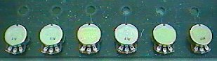
Next I bolt all the pots to a jig I made. It is just a flat piece of junk Plexiglas. You can use anything to make a jig as long as it is not thicker than about
1/8 inch. Other wise you will not have enough threads on your pots to fasten them to your jig. My jig has holes drilled 1 1/2 inches apart from each other and two lines of
holes. 1 1/2 inches is about the widest spacing that you see on chassis. Some chassis have 1 1/4 inch pot hole spacing, the 1 1/2 inch spacing will work on those chassis also.
One line of holes on my jig are for the Mouser style pots. The Mouser pots have a smaller threaded .335 bushing hole size. I have enough holes in each row on my jig to accommodate the longest pot harness. The AB763 board kit with both mid pots has 11 pots so my jig has 11 holes in the CTS row. The longest pot harness that uses mouser pots is 6 pots long. Some pot harnesses have a mix of Mouser and CTS pots. The values for tweed style amps are only available in the Mouser style pot and the values for a Black face type amp are only available in the CTS pots. On the AC30 pot harness I solder a 3 lug terminal strip to the last pot on the right. I snip off 1 lug so that it is now a two lug terminal strip. There is a .0047 cap that has to be soldered to the cut control and a two lug terminal strip seems to do the job nicely. |
 |
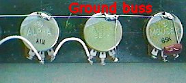 |
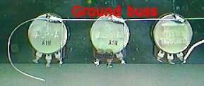
| These photos show a completed pot harness with the ground buss wire soldered to the back of all the pots. The pot grounds are installed. A bright cap and a presence cap are installed and all the pot to pot wires have been installed. I have some detailed photos below of how these hookups are made. | |
 |
 |
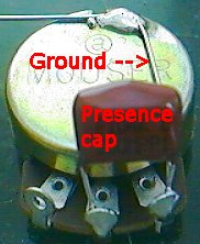 |
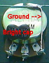
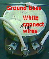
| Pot ground and bright cap | White connect wires | pot ground and presence cap |
|
|
||
|
In all of these photos you can see the ground buss wire that is soldered to the back of all the pots. You will need at least a 40 watt iron to do
this. I start at the last pot at the right end. Notice the upper right photo. You can see the ground buss wire starts in the right hand lug of the pot then goes across the back of
the pot. Then it makes a bend where it is soldered to the back of the 5KL presence pot. From there it continues in a straight line all the way down the line to the back of every
pot. At the left end of the pot harness I leave extra wire hanging out so that the ground buss wire can be soldered to a ground lug on an input jack. Next I connect all the grounds from the pots to the ground buss. Look at the photo on the upper left. There is a short piece of buss wire that goes from the right hand tab on the pot over to the ground buss wire. In the photo, I have it labeled as Ground-->. I stick the buss wire through the pot hole and then make a small loop around the ground buss wire. Then both ends of the ground wire are soldered and the wire is snipped off flush at the pot tab. There are 4 pots in the 5F6A pot harness that need these ground wires added. Look at the layout diagram above. Next I install any caps that are attached to the pots. In the upper left photo and the upper right photo there is a cap on each pot. On the presence cap I do not solder the right hand tab until the cap and the ground wire are installed. Next I install any white connect wires that go from pot to pot. In the layout diagram above you can see that there needs to be two interconnect wires. One is from the 250KL treble pot to the 1MA bass pot and the other is from the 1MA bass pot over to the 25KL mid pot. I use white 20 gauge wire for this. White is the color I use for signal type wires. The upper center photo shows these connect wires. Now your pot harness is done. Undo all the nuts and remove the pot harness from the jig. |
||
Enter My Tube Amp Parts Store Here
Mobile users Enter My Tube Amp Parts Store Here
The Tube amp Library of information
Click the link above for Tube amp info, Schematics, Board building information, Projects, Mods, Transformer diagrams, Photo's, Sound clips.
There are hundreds of pages of Tube amp information on my library page.
Please visit my Tube Amplifier Forum
Here's the place you can go to ask tube amplifier questions.
You will find a large community of friendly amp builders at the link above.
Check the huge library of Schematics here
Design your own custom Turret Board or Eyelet board
DIY Layout Creator file analyzer program
DIY Layout Creator file library
Sound clips and tunes of all types
How to email me
|
MEMBER OF PROJECT HONEY POT Spam Harvester Protection Network provided by Unspam |