
Assembling a Marwi XML LED Bike Light
This page shows how I assemble one of the Marwi XML multi mode LED Bike lights. |
|
| - | |
| Click on the images to see a larger image | |
 |
|
|
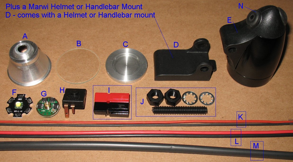
These are all the parts I am using to assemble the Marwi XML lights All these parts are on my web store - See the web store link at the top of this page This page explains what each part is in the picture above I have more info on the Multi mode driver board on this page First we will do some parts prep work like cutting wires, drilling holes, preparing the switch contacts, etc |
|
| - | |
| Click on the images to see a larger image | |
 |
|
|
The solder pads usually have some sort of film over them and must be cleaned. Use an exacto to scrape the surface so that the solder sticks to the pad. Clean one plus and one minus pad on the LED Solder a tiny dome of solder onto each solder pad. See the stack height image down below to see important info about these solder pads. |
|
| - | |
| Click on the images to see a larger image | |
 |
 |
|
I build the XML Marwi's with 3 foot wires Cut the wire to the length you want Trim the black battery negative wire 10mm shorter You can strip the ends and tin the wire at this point. |
The Black and Red silicon wires are used to hook up the XML LED Cut one Black wire and one Red wire, 2 inches long each Strip the silicon jacket 3mm and tin the wires with solder The stripped and tinned ends do not need to be very long |
| - | |
| Click on the images to see a larger image | |
 |
|
|
There's a bunch of prep work on the driver board Left Image Drill a 1/16 inch hole at the top of the board. This where the switch contact gets soldered to the board. Bridge across two legs of the control chip to make the board into a 3 mode board. Just a small blob of solder is all that is needed. Be careful not to heat up the chip legs too much. Blow on the solder to cool it down quickly. You can also use the gold stars on the other side of the chip to select the modes. Jumpering the two chip legs shown above is the same thing as grounding star #3 I have a page of info on these boards that shows how to select different modes using the stars. This page has more info on how this board works. I put a small piece of electrical tape over the non spring side. This keeps the chips from contacting the metal rod and the black negative battery wire. It's not a big deal, the bit of insulating tape just makes me feel better. Middle Image Upper left - This is the LED minus wire location. Clean the green stuff off the board with an exacto and then put a very small solder blob on the board. The black LED wire will get soldered to this point. Solder quickly and blow on it to cool it down quickly so you don't damage the 7135 chip. Right Image I add more solder to the spring base so that it is attached to the board more solidly. Solder the black and red LED wires to the board. |
|
| - | |
| Click on the images to see a larger image | |
 |
 |
|
Switch prep The switch sits at an angle when mounted in the housing. The small switch contact gets bent up so that it is perpendicular to the Heat sink. You can see the bend up angle in the photos above. The large contact gets trimmed off at the hole. Bend the large contact down as shown in the photo. The large contact should not be touching the metal rod when the switch is mounted in the housing. Mount the switch in the housing and slide the metal rod over to lock the switch in place. |
|
| - | |
| Click on the images to see a larger image | |
 |
 |
|
After the switch is locked in place, push the battery wire through the grommet. Solder the black wire to the large switch contact. At this point I add some glue around the grommet and wire to keep them from being pulled out of the housing I use some very thick super glue. This super glue will run out the cracks. The housing must be kept level as the glue sets up. If you can glue the pieces in place the night before you start the final assembly, that is even better. |
|
| - | |
| Click on the images to see a larger image | |
 |
|
|
Slide the board into the small switch contact. The small switch contact fits into the 1/16 inch hole you drilled in the board. Just a tiny bit of the switch contact tip shows through the other side of the board. Solder the switch contact on both side of the board and now the board is locked in place. This switch contact is how the board gets the battery negative from the battery. Bend the Red battery plus wire up and solder it to the spring. |
|
| - | |
| Click on the images to see a larger image | |
 |
|
|
If you pressed the heat sink into the housing yourself, don't forget to drill two small wire holes. The housings I sell already have these two holes. Push the red and black wires into the two holes Slide the metal housing all the way back while pulling the wires forward. I bend the two silicon wires counter clock wise as they exit the holes in the heat sink. I do this because sometimes the LED will twist clockwise as you tighten down the front glass bezel. If the wires are run clockwise, you will be pulling on the wires. Counter clockwise gives you some slack in the wires. I use a small paint brush and add heat sink grease to the heat sink. Then drop the LED into the heat sink. This next part is difficult without a 40 watt or more soldering iron. The reason is that the LED and heat sink are able to suck the heat right out of the soldering iron tip. You need to have a large enough solder iron to avoid this. Solder the Red wire to the LED + Solder the Black wire to the LED - You must keep the solder dome as low as possible or you will short out the wires on the metal reflector. The wire tips must not reach further than the edge of the solder pads. Make sure the stripped wires are not shorting out on the aluminum disc that the LED sits on Important: See the stack height section below |
|
| - | |
| Click on the images to see a larger image | |
 |
|
|
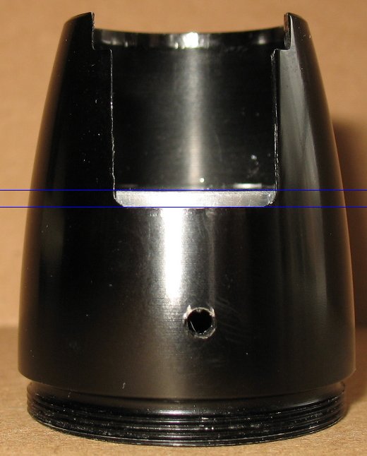
This section is very important The image above shows where the important gaps are This is a side view of what the whole LED stack looks like as it sits in the housing. The front glass bezel pushes against the metal reflector, which keeps the whole stack pushed together tight. See the note down below about how much gap the reflector needs to have I install the heat sinks at the perfect depth to maintain the proper gap. The reflector sits right on the surface of the LED. You must not have large solder blobs that can contact the metal reflector. The wire tips must be kept back away from the reflector. The wire tips should not extend beyond the solder pads. The stripped wires must not contact the aluminum heat sinks In other words, the wires only contact the solder pads and nothing else. This can be very difficult to do, so do it correctly or the light will not work. |
|
| - | |
| Click on the images to see a larger image | |
 |
 |
|
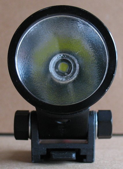
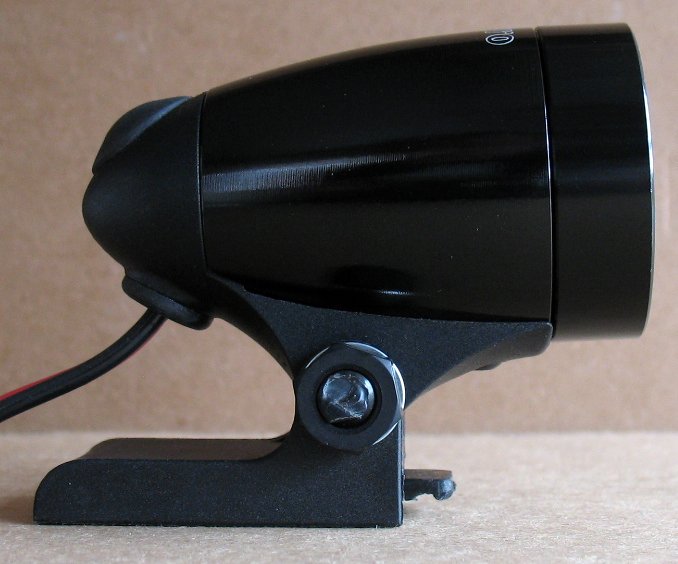
Here's a couple shots of a finished light The front bezel and glass are in place and I have attached the Marwi slide mount The slide mount comes with a Marwi Helmet and Handlebar mount The slide mount is attached to the light with a Marwi mount kit The mount kit is a Nylon threaded rod, Two nylon nuts and two lock washers Using mode 3 on the driver board, this is how the driver and switch work on this light. Click the switch to turn on the light Tap the switch one time to change to the next mode The tapping is just a light tap without clicking the switch All you are doing is disconnecting the switch contacts briefly Each tap goes to the next mode, then the 3 modes start all over again When you click the switch again, the light turns off The last mode you used is remembered by the driver board There are 3 modes of brightness in my build Low mode 1: This mode draws about 130 milliamps of current from the battery I find this mode very useful for just standing around in the dark or when regrouping on a ride I can just barely see the trail using this mode, but younger eyes gather more light. Low mode 2: This mode draws about 800 milliamps of current from the battery I use this mode for long climbs It's perfect for when you don't need the light on full blast High mode: This mode draws up to 2800 milliamps from the battery I use this mode for high speeds and descents Note that battery current draw depends on the battery voltage. A freshly charged battery will run more current than a battery that has been run for one or two hours. The driver board shown on this page can do other modes. There is a link on this page that describes how these boards work. The 3 modes I have selected seem to work the best for most people. All the lights I build only run off of 3.6 volt battery packs. This driver board will not run on 7.2 volt or higher battery packs. I do not have any build info for other types of battery packs because I only use 3.6 volt packs. There are battery pack info links on my main bike light build page. |
|
| - | |
|
Important build info below Heat sink install and reflector gap info |
|
| - | |
| Click on the images to see a larger image | |
 |
 |
|
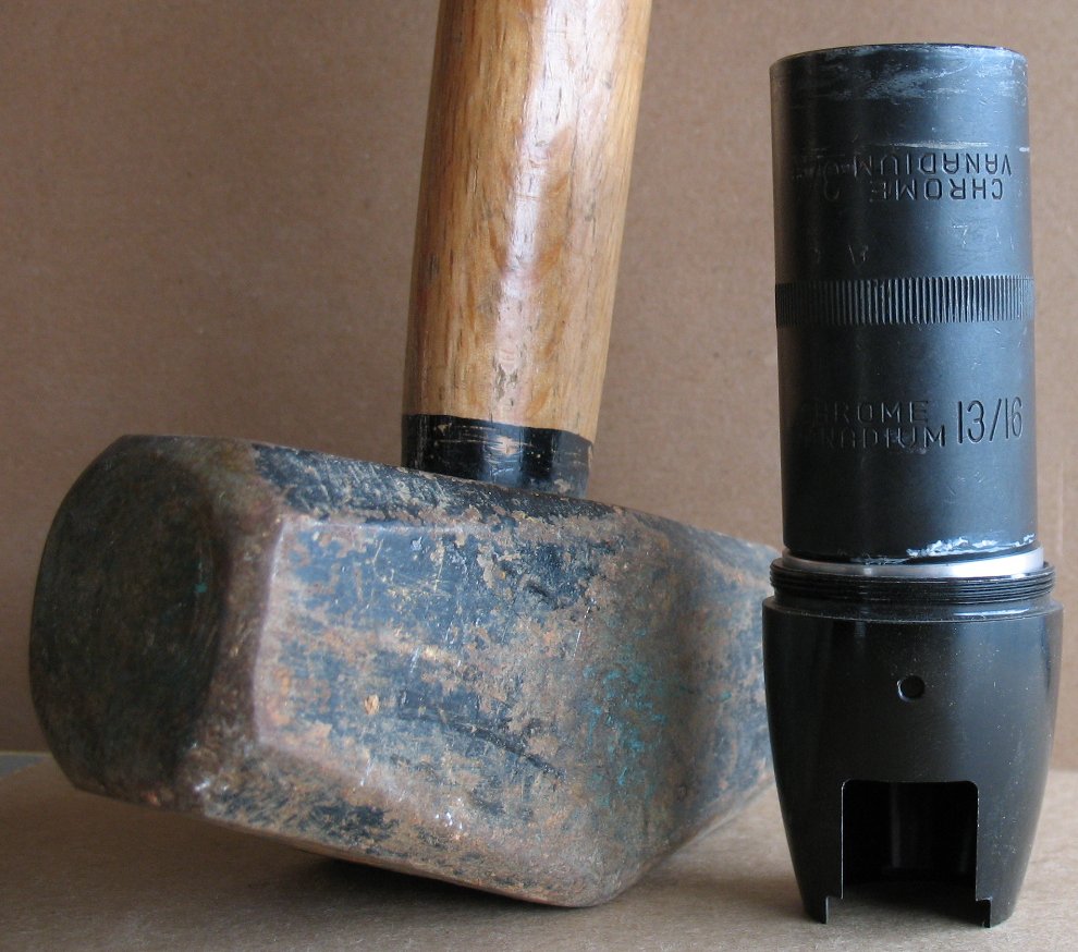
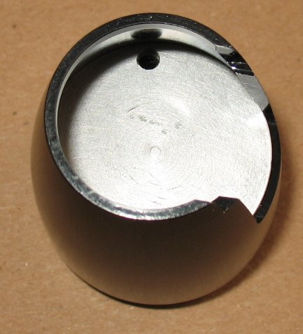
Installing the heat sink Note that I sell the housings with the heat sink already installed to the proper depth But you may prefer to do this yourself to get a different stack height for some other LED or group of parts. Note that I use a press which makes tis a whole lot easier. Tap the heat sink down into the housing using a large diameter socket and a hammer. Look at the big black impact socket I am using It is almost the same diameter as the heat sink Make sure you keep the heat sink level as you tap it down. If one side is farther in than the other, work on the other side to get the heat sink level again. If you start off bad, tap the heat sink out from the other side and start again. Every housing has a tiny bit of difference in the inner diameter. Sometimes the heat sinks go in without much of a fight Sometimes you have to get out a big ass hammer like the one in the picture. If your housing is a bit small, you can sand the outside of the heat sink a tiny bit to get a better fit. Don't make the heat sink diameter too small or you will have to epoxy it in place. I have used this Thermal adhesive and had excellent results Arctic Silver Alumina AATA-5G Thermal Adhesive Don't pound the heat sink in the middle area where the XML will be mounted You may bend the heat sink and then it will not make good thermal contact with the XML When using my machined XML reflector, install the heat sink down as far as it will go The housing walls start to taper and you cannot push the heat sink down any further The pictures above right shows how far down that is. Also see the info above about how much reflector gap you need to have. If you are using some other type of optic/LED combo, you will have to determine how far down to press the heat sink See the section below about the gap I leave between the reflector rim and housing rim |
|
| - | |
| Click on the images to see a larger image | |
 |
 |
|
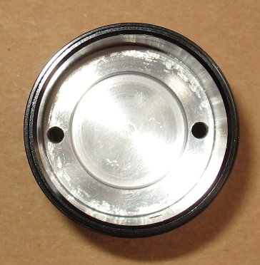
Drill two 1/8" wire holes 180 degrees apart on the outside edges of the heat sink I stock 1/8" drill bits if you need one Drill from the front side where the XML is mounted The holes end up being very close to the inner wall when you flip the housing over and look at it from the back, driver side. De-burr the holes in case there are small bits of aluminum around the holes you drilled |
|
| Click on the images to see a larger image | |
 |
|
|
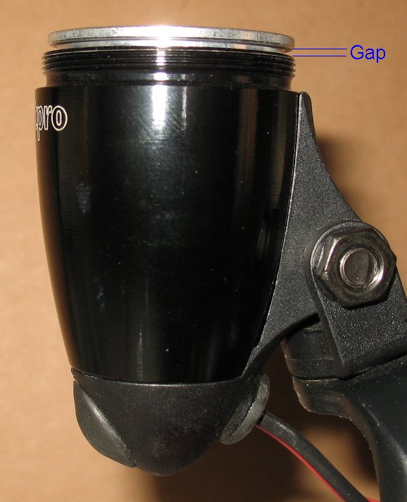
Reflector Gap Info You need to have a small gap between the reflector rim and the housing rim This gap only needs to be 1 mm or 2 mm This gap is there on purpose so that the front glass bezel can put pressure down on the whole LED stack and keep it pressed tight together. The whole stack works like this: The front glass bezel pushes down on the reflector The reflector pushes down on the LED and keeps it tight up against the big aluminum heat sink. The thermal grease carries the heat away from the LED to the heat sink and then to the outer walls of the metal housing. Things to consider if you are installing your own heat sinks. If you screw down the bezel all the way and the glass is rattling, you don't have enough gap at the top. The threads on the bezel are very deep, it will bottom out against the housing rim and will not screw down any further. Adjust the depth of your heat sink if you find that the glass is rattling. If you cannot move the heat sink I have also trimmed off some of the threads on the glass bezel so that the bezel can screw down further I have done this on a small lathe. Not the best solution, but it works |
|
| - | |
Enter My Tube Amp Parts Store Here
Mobile users Enter My Tube Amp Parts Store Here
The Tube amp Library of information
Click the link above for Tube amp info, Schematics, Board building information, Projects, Mods, Transformer diagrams, Photo's, Sound clips.
There are hundreds of pages of Tube amp information on my library page.
Please visit my Tube Amplifier Forum
Here's the place you can go to ask tube amplifier questions.
You will find a large community of friendly amp builders at the link above.
Check the huge library of Schematics here
Design your own custom Turret Board or Eyelet board
DIY Layout Creator file analyzer program
DIY Layout Creator file library
Sound clips and tunes of all types
How to email me
|
MEMBER OF PROJECT HONEY POT Spam Harvester Protection Network provided by Unspam |