
| Back to Library page | |
Fender Power Tube and Bias conversion infoHow to convert a combination cathode/fixed bias system to a fixed bias system.This is one of the procedures that are done when you Black face an amp Black facing generally means converting the amp back to an earlier simple version, like the AB763 circuit |
|
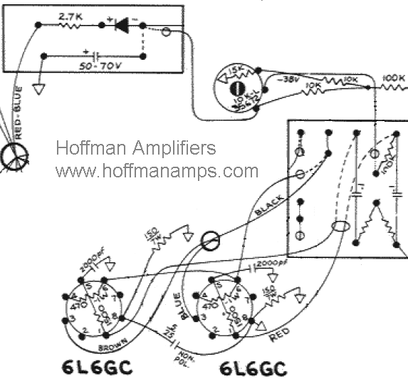 |
Look at all of the extra crap that is attached to the power tubes in this Fender AB568 circuit Want to get rid of it all and convert your power tubes to an older style Fender layout? There are several nasty things going on in this diagram that must be removed in order to return it to an old Fender circuit Nasty #1: The 2000pf capacitors that are attached to pins 5 of each power must go. Clip both of them off right now. They have the effect of shunting high frequencies to ground and making your amp sound dull. Nasty #2: The 150 ohm 7 watt resistors that are attached to pin 8 of both power tubes must go. Unsolder them from pin 8 and clip them off at the chassis solder joint. Nasty #3: The 5uf/25 volt capacitor that goes from pin 8 on one power tube, over to pin 8 on the other power tube must go. Unsolder it at both ends and remove it. |
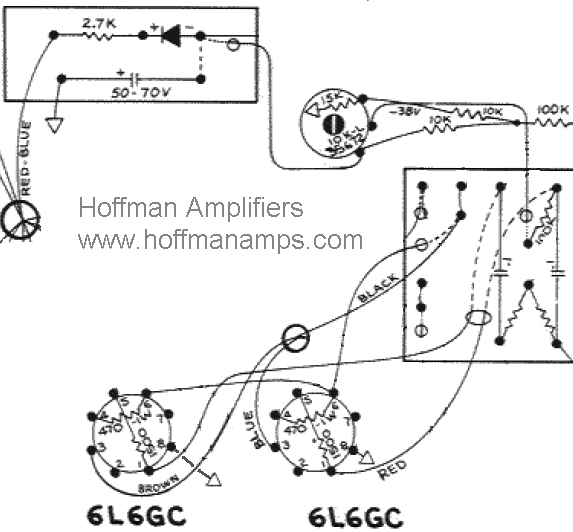 |
In this diagram, all of the nasty bits mentioned above have been removed and you are back to a simple Fender power tube setup. The left hand power tube now shows pin 8 as going to ground. I do not recommend soldering a ground to a chassis. I would run a wire from the left hand pin 8 to the right hand pin 8. The right hand tube ground should already be there. Better yet, solder a wire to pin 8 and then solder a round ring terminal to the other end. Bolt the ring terminal to the closest power transformer mounting bolt to make a good ground connection. You can do this to both power tubes if you like. Note: You will have to re-bias the amp since everything has been changed. The bias system in the diagram is a bias balance system. If you have a bias balance, you may want to convert it also. That mod is covered on this page |
Enter My Tube Amp Parts Store Here
Mobile users Enter My Tube Amp Parts Store Here
The Tube amp Library of information
Click the link above for Tube amp info, Schematics, Board building information, Projects, Mods, Transformer diagrams, Photo's, Sound clips.
There are hundreds of pages of Tube amp information on my library page.
Please visit my Tube Amplifier Forum
Here's the place you can go to ask tube amplifier questions.
You will find a large community of friendly amp builders at the link above.
Check the huge library of Schematics here
Design your own custom Turret Board or Eyelet board
DIY Layout Creator file analyzer program
DIY Layout Creator file library
Sound clips and tunes of all types
How to email me
|
MEMBER OF PROJECT HONEY POT Spam Harvester Protection Network provided by Unspam |