
| Back to Library page |
Power supply Filter cap solutions |
| There is more helpful info on the library page here |
| - |
 |
|
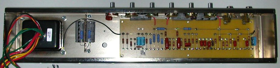
Above are the two most common filter cap arrangements you find on Fender amps The caps are mounted on a filter cap board on the back of the chassis A metal cap can covers the cap board Left: Stage 1 is two 20uf caps in parallel making 40uf total at 500 volts working voltage Stages 2, 3 and 4 are single 20uf caps Right: Stage 1 is two 100uf caps in series with 220k balancing/bleeder resistors This arrangement makes 50uf with a 700 volt working voltage Stages 2, 3 and 4 are single 20uf caps The 1k and 4.7k / 3 watt power supply resistors are shown I do not stock pre made filter cap boards but you can make your own. Drill some holes in a board at the ends of each cap Install Turret lugs or eyelets in the holes Drill some mounting holes in the board Use some sort in insulating backing board so the electrical connections cannot short out on the metal chassis Screw down the board Screw the cap can over the top of everything making sure no electrical connections can short out on the metal cap can This method is a bunch of work But there are other methods you can use to construct your filter caps I show two of those methods below All of the parts shown below can be found in my on line parts catalog here. |
| - |
| Power supply Filter cap solutions - Method One |
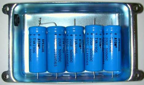
| This method does not use a circuit board or insulating backing board. I will be using 5 x 20uf/500v Sprague atom filter caps. The negatives of all the caps are soldered to the can itself and then the can must be screwed down tight to the back of the chassis so that the four corners of the can make good contact with the chassis. That way you will get a good ground contact between the can and the chassis. The positive ends of the caps are clipped short. There will be four positive wires that are soldered to the filter caps and then exit out of the can through a rubber grommet. The four wires go to each of the four filtration stages. You can secure the caps to the metal can with double stick tape, glue or RTV silicon. |
 |
|
Here you can see that I have taken a small Fender cap can and drilled 5 holes 1 hole for each of the cap negative wires. |
| - |
 |
|
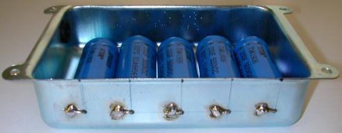
Push the negative leads of each cap through the drilled holes. Bend them 90 degrees and then clip them to about 10cm or roughly 3/8 inches. Solder all the negative leads to the filter can. You may need a 40 watt or more soldering iron to be able to solder the leads properly. The metal can will suck the heat right out of a small soldering iron. |
| - |
 |
|
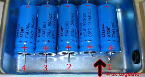
(1) Twist the first two capacitors positive leads together to make two 20uf capacitors in parallel. This is the first stage of filtration downstream from the rectifier. 20uf + 20uf = 40uf total filtration on stage one. (2-3-4) Stages 2 through 4 are single 20uf/500v caps that will go to the board |
| - |
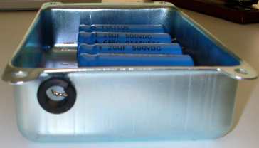 |
| Here you can see that I took a 1/2 inch grommet and cut out a small wedge
so that it would fit into the smaller diameter cap can hole. Solder 4 x 18 gauge stranded red wires to the ends of the caps Use some 3/16 inch heat shrink to seal the solder joints The four positive wires exit through this grommet and go inside the amp to the circuit board. You may have to drill a hole in the chassis where the four wires enter The cap can can be screwed down to the chassis using #8 tapping screws |
| - |
| Power supply Filter cap solutions - Method Two | |
| Here is another way to do the filter caps without a cap can or circuit board. All the filter caps are inside the chassis going point to point. The stage one filter caps are between the power transformer and the circuit board on an 8 lug terminal strip. The remaining three stages are along the front edge of the chassis, under the pot harness. |
|
| - | |
 |
|
| Here you can see the whole chassis and all five filter caps. The main filter caps are shown to the left of the board. The other 3 stages are under the pots |
|
| - | |
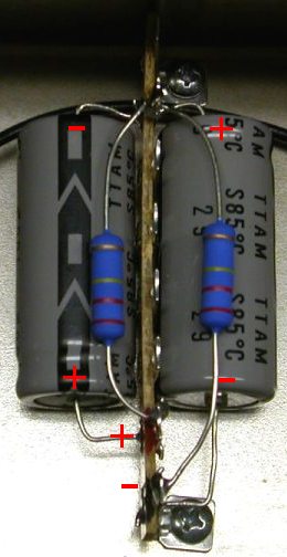 |
These are the two main stage one filter caps mounted to an 8 lug terminal strip. I have done a series arrangement here of two 100uf/350v caps. You could do a parallel arrangement here also. The bottom lug on the terminal strip, and the top lug of the 8 lug terminal strip are bolted to the choke holes in the chassis. The choke is on the other side of the chassis bolted to the same holes. The 220k/3 watt resistors are bleeder resistors. The bottom lug on the terminal strip acts as the chassis ground connection for the filter caps. You can also solder a wire here and ground that on a transformer bolt with all the other grounds. Lug #2 is the main B+ connection. Lug #7 is where the two caps and two resistors are all soldered. Lugs 3, 4, 5, 6 and 8 are not used. Note that the top lug, #8 of the terminal strip is not connected to anything, it is just used to bolt down the terminal strip You can see more info about parallel and series cap arrangements on the library page here. |
| - | |
 |
|
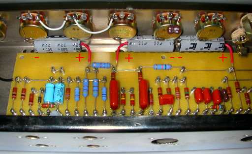
| Here you can see the last 3 stages of filtration. The positive ends of the caps go right to the lug on the circuit board so no wire is needed. The negative ends are all soldered to the buss wire that runs down the back of the pot harness, so no wire is needed I have put some #18 gauge red wire jacket on the positive ends of the cap leads as a safety feature. The caps are all tucked neatly under the pots and out of the way. Illinois caps and F&T caps are small enough to mount this way Sprague atom caps are too large to mount this way. |
|
| - | |
Enter My Tube Amp Parts Store Here
Mobile users Enter My Tube Amp Parts Store Here
The Tube amp Library of information
Click the link above for Tube amp info, Schematics, Board building information, Projects, Mods, Transformer diagrams, Photo's, Sound clips.
There are hundreds of pages of Tube amp information on my library page.
Please visit my Tube Amplifier Forum
Here's the place you can go to ask tube amplifier questions.
You will find a large community of friendly amp builders at the link above.
Check the huge library of Schematics here
Design your own custom Turret Board or Eyelet board
DIY Layout Creator file analyzer program
DIY Layout Creator file library
Sound clips and tunes of all types
How to email me
|
MEMBER OF PROJECT HONEY POT Spam Harvester Protection Network provided by Unspam |