| Simple Bias Current Checker:
Basically the way this thing works is that pins 1,2,3,4,5 and 7 pass uninterrupted through the device from tube base to
tube socket.
Pin 6 is not used and so there is no need to wire it up.
Pin 8 from the tube base is sent out to a Multimeter set to dc milliamps and sent back to pin 8 of the tube socket.
You are basically reading the current flowing through pin 8 by putting your meter in line with it.
You can see the current flow in the diagram above.
The current flows up from pin 8 of the tube base, out through the multi meter and then from the multi meter to pin 8 of
the tube socket.
The meter is set to DC milliamps and the range is set to under 200 ma on the meter.
How to build the Bias Current Checker:
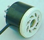
Sand out the inside of the tube base if necessary so that the tube socket will fit down into the tube base.
Do not try to force the tube socket into the base, the base is Bakelite and will crack.
Trim the tube socket pins to about half their length so the pins do not hit the bottom of the tube base.
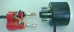
Solder a 2 inch or longer bare wire to pins 1 through 7 on the tube socket.
A small hole has to be drilled in the side of the tube base down near where pin 8 meets the base.
You need a two conductor wire to exit out that hole and go to a double banana plug.
I use the mini shielded cable for the wire.
Solder the two conductors of the cable, one to pin 8 on the tube base and one to pin 8 on the tube socket.
Push the whole contraption together so that wires soldered to pins 1 through 7 on the tube socket come out the bottom
of pins 1 through 7 on the tube base. (They are hollow)
Solder pins 1 through 7 at the tips of the tube base pins.
Solder a double banana plug to the other end of the two conductor cable.
I poured epoxy down inside the sockets to make them solid on mine, but this in not necessary. You do not want to get epoxy
inside the area where the tube plugs in or your socket will be ruined.
Click here to enter my parts
catalog shopping cart.
Materials list for each Bias Current Checker
These items are located on my Tube sockets page
1 - 8 Pin ceramic Marshall style tube socket.
1 - 8 Pin tube socket base.
This item is listed on my Wire/Cable page.
2 - feet of mini shielded cable.
This item is listed on my Jack/Plugs page.
1 - Double banana plug.
How to use the Bias Current Checker:
* Plug your Bias Current Checker into a tube socket on an amp.
* Plug your power tube into the Bias Current Checker.
* Plug the banana plug into your Multimeter. Make sure you plug into the two holes that are for current measurement in
the under 200ma range. You do not want the high amp range.
* Set your Multimeter to DC milliamps (under 200ma range).
* Turn on the amp and let it warm up in standby mode.
* Take the amp off standby. (Be ready to quickly put it back on standby if the current is too high.)
* Turn the bias pot till you get somewhere around 35 milliamps of current. (Generic setting)
* Check next power tube and split the difference if they are off just a bit.
Notes: If you have 38ma on one tube and 34 ma on another, they are still close enough to be called a matched pair. If
you are off more than 8 or 10ma, that is not a real good matched pair. Differences in the tube sockets can be the culprit
also, so you must swap the tubes around and read them in different sockets to figure out what is going on.
If you do not have a bias pot, you will have to figure out where the fixed resistor is in the bias circuit that controls
the bias. It is a resistor that will be able to read the negative bias voltage on one end and is connected to ground on
the other end.
You have to change the bias resistor to a larger value for less bias current (more bias voltage) and a smaller value for
more bias current (less bias voltage).
The end
|