
| Back to Library page | |
Common Hookup info for layout diagrams #1 - Old layout diagrams |
|
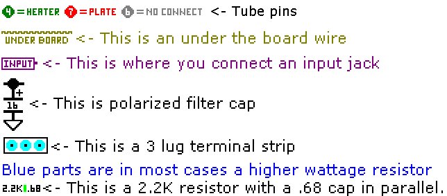 |
This drawing shows common hookup info codes used on my layout diagrams. Notes: No connect is a pin on a tube that is not connected internally. You can use these pins as terminal connectors since they just dead end and do not enter the tube. Note that a bias caps polarity is reversed because you are filtering negative voltage. |
| Drawing scale issues | |
 |
 |
| The layout diagram | The actual circuit board holes |
| Some of the components on my old layout diagrams take up a lot of space on the drawing. I have to wedge these components into the layout drawing any way I can. Examples: The 100k resistor circled in red looks longer than the .1 capacitor right above it. The lug spacing looks closer together on the .1 than the 100k. The actual board holes for these parts are shown in the image above right Note that the .1 and 100K holes are spaced evenly on the board. The blue 22k resistor on the layout diagram shows that it crosses a long gap. There is no long gap on the actual circuit board where the blue 22k resistor gets installed. All four lugs to the right of the 22k get laced together You can hook the right side of the 22k resistor to any one of those four lugs. |
|
| Common Hookup info for layout diagrams type 2 - Newer style layout diagrams |
 |
| Layout diagrams #2 - newer style |
| The newer style layout diagrams are taken from the same CAD program I use to make the pre-drilled
boards The turret lug layout on these diagrams is exactly like it is on the pre-drilled boards I sell. Many of the drawing parts are explained on the image above. Note that a bias caps polarity is reversed because you are filtering negative voltage. |
| Bending lug leads on long bodied parts | |
 |
If you have components that are longer than the lug to lug distance, bend the leads like the picture on the left. |
| Removing the death cap | |
 |
The purple .047 cap in this drawing is know as the "Death cap". Many a guitar player
has been shocked on a microphone because of this cap. If you have a 3 prong grounded power cord and it is installed properly, you do not need, or you can remove the purple parts from your amp. The green power cord ground wire must be grounded to the metal chassis so that your amp is tied to ground properly. The parts you do not need are the ground switch and the cap that is connected to this switch. Many people use the ground switch hole on a chassis for a standby switch. |
| Input jack wiring | |
 |
Hi/Lo jacks: This is a diagram of a Hi/Lo jack pair. One pair usually goes to valve one, Pin 2. The other pair usually goes to valve one, Pin 7. |
 |
Hi/Lo jacks: The photo to the left shows a Hi/Lo pair of jacks. Two Switchcraft 12A jacks are arranged with the solder tabs lined up. The red dots indicate where there will be solder connections made. The #1 jack on the right is the High input jack. The #2 jack on the left is the Low input jack. Note: I do not solder the joining tabs outside the amplifier because they may not line up with the amplifiers holes properly. I solder the tabs in place inside the amp itself. |
 |
Single input jack: You can also just use one input jack, you do not have to have a Hi and Lo input. The 68K can be other values like 33K, 47K, etc. |
 |
<- Click on the image to see a larger image. Diagram, courtesy of Sluckey |
| Heater hookup |
 |
| The 6.3 volt heater wires come out of the power transformer and they go right to a light bulb
fixture to power the pilot lamp. This is a common arrangement on Fenders. The lamp is a convenient terminal on the way
to the power tubes. From the lamp you can then run a twisted pair of 18 Gauge wires over to the first power tube. Pins
4 and 5 are jumpered together on 12A*7 type pre amp tubes. 20 Gauge wire is fine for the pre amp tubes. If you
do not have a heater center tap on your power transformer, you must run two 100 ohm 1/2 watt resistors to ground to create
an artificial center tap. If you do not have a center tap, you will get 120 cycle hum. Each 100 ohm resistor is soldered
to one of the heater wires. The other ends of the 100 ohm resistors are twisted together and then soldered to ground.
The heater wires are usually run up in the air, above the tube sockets in a twisted pair. Twisting the heater wires cancels hum. This is why phone line wires are run in twisted pairs. The twisted pair wires drop down and get soldered to the tube socket pins. The twisted pair continues down the line to every tube in the chain. Keeping the wires in phase helps with hum sometimes. In other words, pin 7 on one power tube goes to pin 7 on the next power tube. Pin 9 on a pre amp tube goes to pin 9 on the next pre amp tube. EL84 power tubes heater connections are pins 4 and 5. Most other 8 pin power tubes use pins 2 and 7. |
| Power transformer hookup and rectifier info |
 |
| Note: I am not showing any bias windings or bias taps on any of the above diagrams. |
| Half wave rectifier circuit - This circuit is found on the old 6G15 Fender stand alone reverb units. It produces very rough DC voltage and needs lots of filtering to smooth it out. The transformer does not need a 5 volt tube rectifier filament winding since there is no tube rectifier. It is very cheap to set up but all you save is 3 diodes and the DC is so rough that you have to filter the crap out of it. |
| Full wave diode rectifier circuit - This circuit produces DC voltage that is twice
as smooth as the half wave circuit. It requires a center tap on the high voltage winding. The transformer does not need
a 5 volt tube rectifier filament winding since there is no tube rectifier. If you measure the AC voltage across the two Red AC windings you will usually see about 700 volts AC. You may end up with roughly 400 plus volts DC coming off the rectifier, depending on the winding current spec's for the high voltage winding. The larger the current rating, the less of a voltage drop you will get under load. |
| Full wave tube rectifier circuit - This circuit produces DC voltage that is twice
as smooth as the half wave circuit. It requires a center tap on the high voltage winding. The transformer requires a 5
volt tube rectifier filament winding to heat the tube rectifier filament. If you measure the AC voltage across the two Red AC windings you will usually see about 700 volts AC. You may end up with roughly 400 plus volts DC coming off the rectifier, depending on the winding current spec's for the high voltage winding. The larger the current rating, the less of a voltage drop you will get under load. |
| Full wave bridge rectifier circuit - This circuit produces DC voltage that is 2 times
as smooth as the half wave circuit. It needs way less filtering than a half wave circuit and has the added advantage of
not needing a center tap on the high voltage winding. The transformer also does not need a 5 volt tube rectifier filament
winding. If you measure the AC voltage across the two Red AC windings you will usually see about 350 volts AC. You may end up with roughly 400 plus volts DC coming off the rectifier, depending on the winding current spec's for the high voltage winding. The larger the current rating, the less of a voltage drop you will get under load. NOTE: Notice that the high voltage winding AC voltage is roughly half that of the full wave rectifier. |
| Making a 4 power tube board |
 |
| The blue parts have been doubled in the diagram above. |
| You can make a 4 power tube version of any board. I don't sell 4 power tube mask because
it's easy for you to make a 4 power tube board if you already own a two power tube mask. You must own my drilling
template and a mask to be able to do the procedure described here. Basically, all you are doing is adding two more 1 ohm cathode resistor spots and two more screen resistors spots to your board. You must plan ahead by making your board longer by 4 more lug places horizontally. You can also just drill the board and then trim it to length after you are done. This is the foolproof method. As you are drilling the board left to right or from the pre amp end towards power tube end, you must stop when you get to the area where the 1 ohm cathode resistors and screen grid resistors are. You go ahead and drill the normal 4 spots it takes for a two power tube board. Then you just shift the mask to the right four places. Once the mask has been moved you can drill the 1 ohm and screen grid resistor holes again. Now you should have 4 x 1 ohm resistor spots and 4 x screen grid resistor spots. You can leave the mask where it is and drill the remaining holes to the right. If there is a bias pot on your board, the template should be correct because I designed it to be able to do two or 4 power tube versions of the boards. If your board has negative feedback, you will have to change the value of the feedback resistor to two times the normal value. Example: a 50 watt Marshall has a 47K feedback resistor and a 100 Watt Marshall has a 100K feedback resistor. |
Enter My Tube Amp Parts Store Here
Mobile users Enter My Tube Amp Parts Store Here
The Tube amp Library of information
Click the link above for Tube amp info, Schematics, Board building information, Projects, Mods, Transformer diagrams, Photo's, Sound clips.
There are hundreds of pages of Tube amp information on my library page.
Please visit my Tube Amplifier Forum
Here's the place you can go to ask tube amplifier questions.
You will find a large community of friendly amp builders at the link above.
Check the huge library of Schematics here
Design your own custom Turret Board or Eyelet board
DIY Layout Creator file analyzer program
DIY Layout Creator file library
Sound clips and tunes of all types
How to email me
|
MEMBER OF PROJECT HONEY POT Spam Harvester Protection Network provided by Unspam |