
| Back to Library page | |
How to make and use a Bias Current CheckerMore recent bias checker versions can be found on the library page |
|
| - | |
| Click on the images below for a larger image | |
 |
|
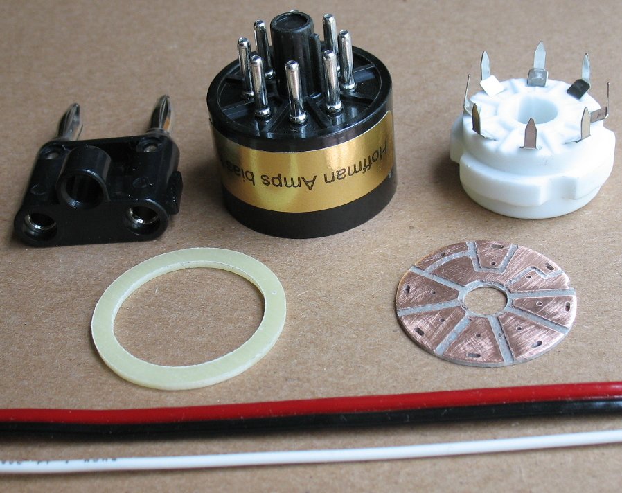
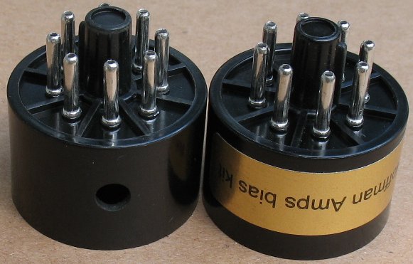
| Left: Bias Checker Parts Right: The tube bases are now coming with the 7/32 inch hole already drilled and a nice gold sticker |
|
Materials list for each Bias Current Checker 1 x Dual banana plug 1 x 8 pin tube base 1 x 8 pin PC board tube socket 1 x Bias checker Ring and copper board 1 foot of 18 gauge zip cord 2 feet of 20 gauge wire to be used as buss wire The bias checker can be ordered as a kit on this page in my parts catalog Tube Sockets page |
|
|
|
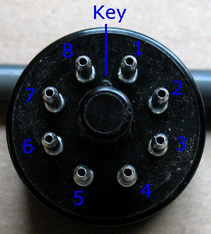
How it works The way this Bias checker works is that pins 1,2,3,4,5,and 7 pass uninterrupted through the Bias Checker from the tube base to the tube socket. Pin 6 is not used in most 8 pin tubes and so there is no need to wire it up. Pin 8 from the tube base is sent out to a Multimeter set to dc milliamps and sent back to pin 8 of the tube socket. You are basically reading the current flowing through pin 8 by putting your meter in line with it. You can see the current flow in the diagram above left. The current flows up from pin 8 of the tube base, out through the multi meter and then from the multi meter to pin 8 of the tube socket. The meter is set to DC milliamps and the range is set to under 200 milliamps on the meter. |
|
| - | |
| How to build the Bias Current Checker | |
| Click on the images below for a larger image | |
 |
|
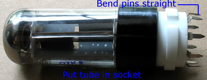
Insert a 8 pin tube into the 8 pin PC socket. This is done so that all the pins line up properly. You may not be able to get a tube into the socket later if you do not insert one now. Bend the tube socket pins so that they are straight up, so they will line up with the circuit board holes properly. |
|
| - | |
| Click on the images below for a larger image | |
 |
|
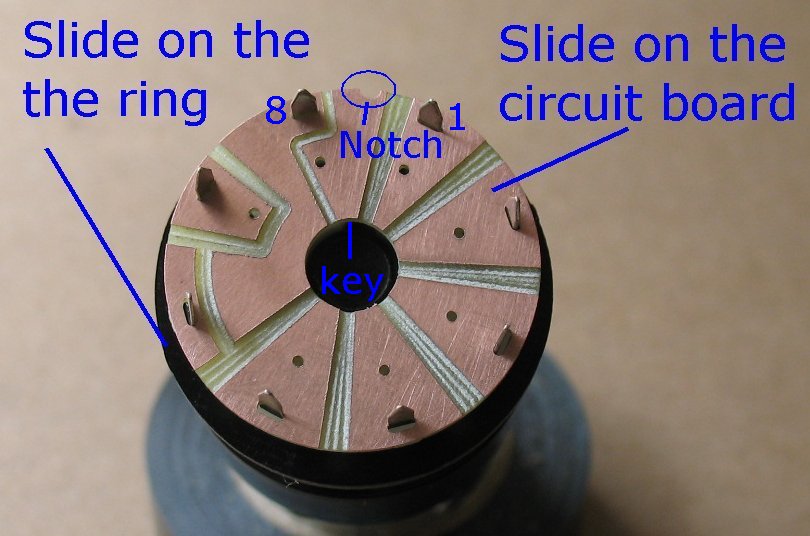
Slide on the Ring now - If you forget to do this now, it will be too late later. I like to super glue the ring to the socket now, so it becomes part of the socket. The ring helps center the tube socket on the tube base and gives the tube socket a nice place to rest. De-Burr the copper circuit board, sand the edges if needed. The CNC machine sometimes leaves small bits of copper. Some of the copper edges may need to be trimmed or checked to make sure no small copper pieces are going to short out across the gaps. Copper oxidizes and so the copper may need a bit of steel wool or fine sandpaper to clean it up and make it shiny. Solder will stick way better to clean copper. Slide the circuit board onto the Tube socket pins. Line up the small notch on the circuit board. This notch goes between Pin 1 and Pin 8 on the tube socket. The key on your tube and tube socket should be pointing to this notch |
|
| - | |
| Click on the images below for a larger image | |
 |
|
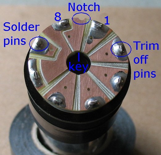
| Solder all the pins Trim off the extra pin lengths |
|
| - | |
| Click on the images below for a larger image | |
 |
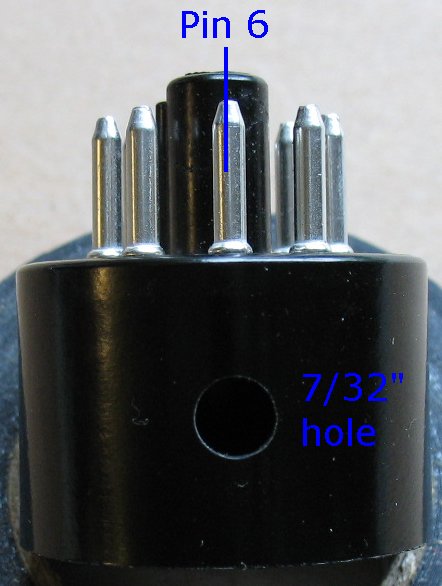 |
The bases I currently sell have the hole already drilled in the proper place. See the image of the new bases at the top right of this page. Drill a hole in the base if there is not already a hole. Pin 6 is not used on most 8 pin power tubes and so this makes a great place for the wire to enter the tube base. Take your tube base and drill a 7/32" hole right in front of Pin 6 about half way down the side of the tube base. Drill slow and carefully, the tube base is made of a brittle material that will crack if you apply too much drilling pressure. You can use other drill sizes if you do not have a 7/32" drill. 7/32" just happens to work out great for the Red/Black zip cord I send with the kit |
|
| - | |
| Click on the images below for a larger image | |
 |
|
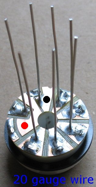
The holes in the circuit board are drilled for 20 gauge wire Cut 7 pieces of 20 gauge wire about 2" long, or you can use a spool of buss wire. Strip the insulation off the 20 gauge wire. Gently push the 20 gauge wires down into the 7 holes as far as they will go. There is nothing behind the board they can short out on. The 20 gauge wires should stand up in the air by themselves, which makes them easier to solder. Solder the 7 wires into the 7 holes on the circuit board. Pin 6 does not have a hole. The Black and Red dots are where you are going to solder the Black/Red zip cord |
|
| - | |
 |
|
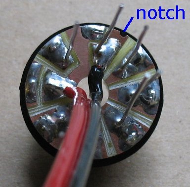
Solder the Black/Red zip cord to the circuit board. See the picture up above with the red and black dots. It helps if the Red wire is cut just a tiny bit shorter than the black wire. The black wire is soldered to the tab where the notch is. The red wire is soldered where Pin 6 would be, if Pin 6 had a wire Make sure your solder connections are clean and that there is no way a wire or solder blob can short out onto another part of the circuit board. Make sure you do not use too much solder and jumper across the circuit board copper sections. |
|
| - | |
| Click on the images below for a larger image | |
 |
|
| Slide the tube base onto the zip cord through the hole you drilled | |
| - | |
| Click on the images below for a larger image | |
 |
|
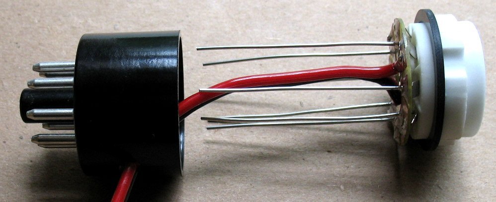
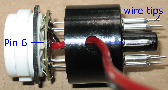
This part can be a bit tricky so take your time. You have to rotate the tube base and the tube socket circuit board assembly so that pin 6 is in a straight line. Move the two items closer together and align all 7 of the 20 gauge wires so they go through the pin holes on the tube base. The technique is to pull a bit of the zip cord, pull everything closer, pull some more zip cord, pull everything closer, etc It helps if you can guide the 7 wires into the tube base holes with a small set of needle nose pliers or some sort of dental pick device. When you get it right, the 7 wire tips will be sticking out the bottom of the tube base pins. Double check to make sure all 7 wires are in the correct holes in the tube base. |
|
| - | |
| Click on the images below for a larger image | |
 |
|
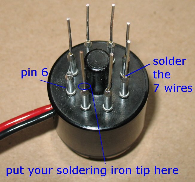
After you have made sure the 7 wires are in the correct holes, push the whole assembly together tight. This would be a good time to apply some super glue to both sides of the ring as you push the assembly together. This will keep the tube socket assembly from twisting inside the tube base. You could also use some epoxy. If you glued the ring to the tube socket earlier, you only have to glue the ring to the tube base. Solder all 7 wires to the tube base pins. You solder the wires by touching your hot soldering iron to the 20 gauge wire very close to the tube base pin. As soon as the wire is hot enough , touch your solder to the wire and it will follow the wire down into the tube base pin. You do not apply the solder to the outside of the tube base pin. It's a delicate operation and one that takes a bit of practice to get good at. Your soldering iron tip should be very pointy and very close to the tube base pin so that the pin gets just as hot as the wire does. The Solder will follow the heat, you do not have to stuff the solder into the hole. If you blob solder all over the outside of the tube base pin, you will not be able to push it into a tube socket on your amp. If you do blob a bit of solder, you should clean all the solder off the tip of your soldering iron. Then heat up the tube base pin and wipe the solder off while the solder is still hot. You can also use an exacto knife or razor blade to gently slice off the solder. |
|
| - | |
| Click on the images below for a larger image | |
 |
|
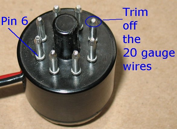
| Snip off all the 20 gauge wires after you have soldered them | |
| - | |
| Click on the images below for a larger image | |
 |
|
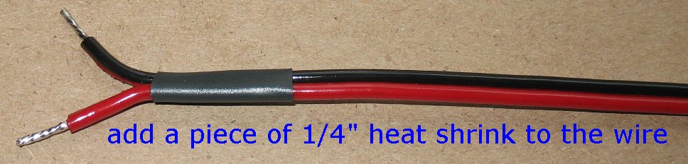
| Adding a bit of heat shrink to the wire is optional. You could add heat shrink on the tube base end also where it enters the tube base hole. |
|
| - | |
| Click on the images below for a larger image | |
 |
|
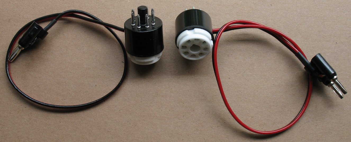
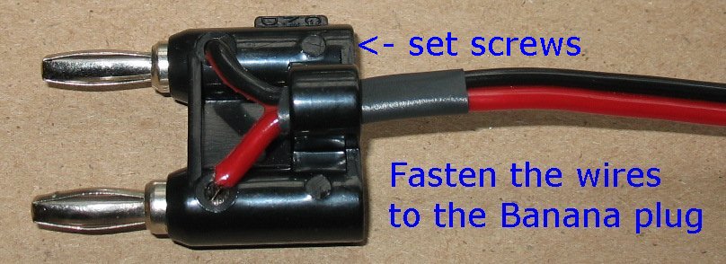
| Loosen both set screws on the banana plug. Push in the black and red wires. Tighten down the set screws. You can install the wires into banana plug any way you like. If you plug it into your meter one way, you will be reading negative current flow If you plug it into your meter the other way, you will be reading positive current flow. If your meter only works one way, you will have to make a note which way to plug it in. Dual banana plugs have a 3/4 inch center to center spacking If your meter has a different spacing you can use individual banana plugs I sell Red and Black single banana plugs on this page 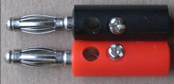 |
|
How to use the Bias Current Checker Plug your Bias Checker into a tube socket on an amp. Plug your power tube into the Bias Checker. Plug the banana plug into your Multimeter. Make sure you plug the banana plug into the two holes on your meter that are for DC current measurement. Set your Multimeter to DC milliamps in the under 200ma range. Turn on the amp and let it warm up in standby mode, if it has a standby. Take the amp off standby. Be ready to quickly put the amp back on standby if the current is too high. Turn the bias pot until you get somewhere around 35 milliamps of current. 35ma is a Generic setting Remove the bias checker and move it to the next tube. Put the first tube back into the tube socket. Check the next power tube and split the difference if they are off just a bit. You cannot check the bias properly unless all the power tubes are installed and running. Each power tube pulls a certain amount of current and this alters the overall voltage on the power supply. If you try and read the bias with some of the power tubes out of the amp, you will not get a proper current reading. Example of a bias reading If you have 38 ma on one tube and 34 ma on another, they are still close enough to be called a matched pair. If you are off more than 8 or 10ma, that is not a real good matched pair but the amp will work. Different current readings between each of the power tubes can be caused a couple different things. It could be the tubes themselves or the parts connected to each tube socket can alter the current readings. You must swap the tubes around and read them in different sockets to figure out what is going on. If a tube reads differently in a different socket, then you can assume it's not the tube. Screen grid resistors can drift and cause altered current readings. The output transformer windings can also be the problem. The bias supply can be sending different negative voltage levels to each tube. If you do not have a bias pot, you will have to figure out where the fixed resistor is in the bias circuit that controls the negative bias voltage. It is a resistor that will be able to read the negative bias voltage on one end and is connected to ground on the other end. You have to change the bias resistor to a larger value for less bias current (more bias voltage) and a smaller value for more bias current (less bias voltage). One bias checker for each power tube in your amp would be the ideal situation. The problem with this is that you have to have some sort of switching situation that re-connects a tube after you switch to the next tube. I made such a thing years ago after finding a multiple push button switch that was able to switch properly. I suppose you could also have multiple meters running at the same time and read multiple tubes at the same time. There is more info on biasing on the library page. You can also go to my tube amp forum for help, the people on my forum are very knowledgeable |
|
Enter My Tube Amp Parts Store Here
Mobile users Enter My Tube Amp Parts Store Here
The Tube amp Library of information
Click the link above for Tube amp info, Schematics, Board building information, Projects, Mods, Transformer diagrams, Photo's, Sound clips.
There are hundreds of pages of Tube amp information on my library page.
Please visit my Tube Amplifier Forum
Here's the place you can go to ask tube amplifier questions.
You will find a large community of friendly amp builders at the link above.
Check the huge library of Schematics here
Design your own custom Turret Board or Eyelet board
DIY Layout Creator file analyzer program
DIY Layout Creator file library
Sound clips and tunes of all types
How to email me
|
MEMBER OF PROJECT HONEY POT Spam Harvester Protection Network provided by Unspam |