
| Back to Library page |
What is a Hoffman Board?Note that information on this page dates back to prior to the year 2000I am leaving it on my web for informational purposes Many years ago, I made replacement turret boards for printed circuit board amps. After my parts business took off, I was not able to make the Hoffman boards because shipping out parts took all my time. I then came up with a way that others could manufacture the Hoffman boards. The information further down the page is the information from my web site when I used to sell the Hoffman boards. Note: I do not make complete Hoffman boards. I do not sell all the parts as a kit. Complete boards are manufactured by authorized manufacturers. You can see a list of these authorized manufacturers on the page below. Contact the people on the page above if you are interested in purchasing a complete Hoffman board. Click here for Authorized Hoffman board kit manufacturers Here's a few images of a 5F6A board front and back You can click on the images to see larger images 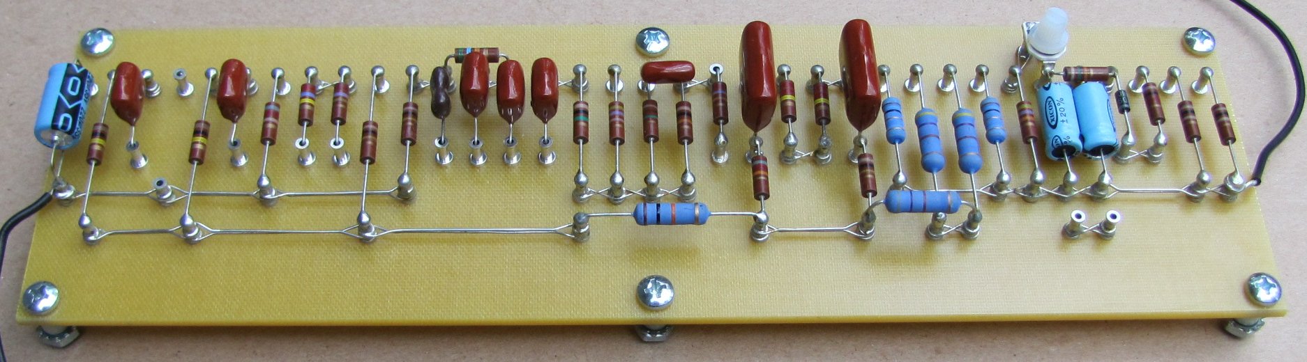 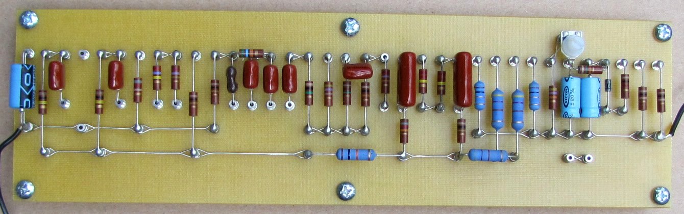 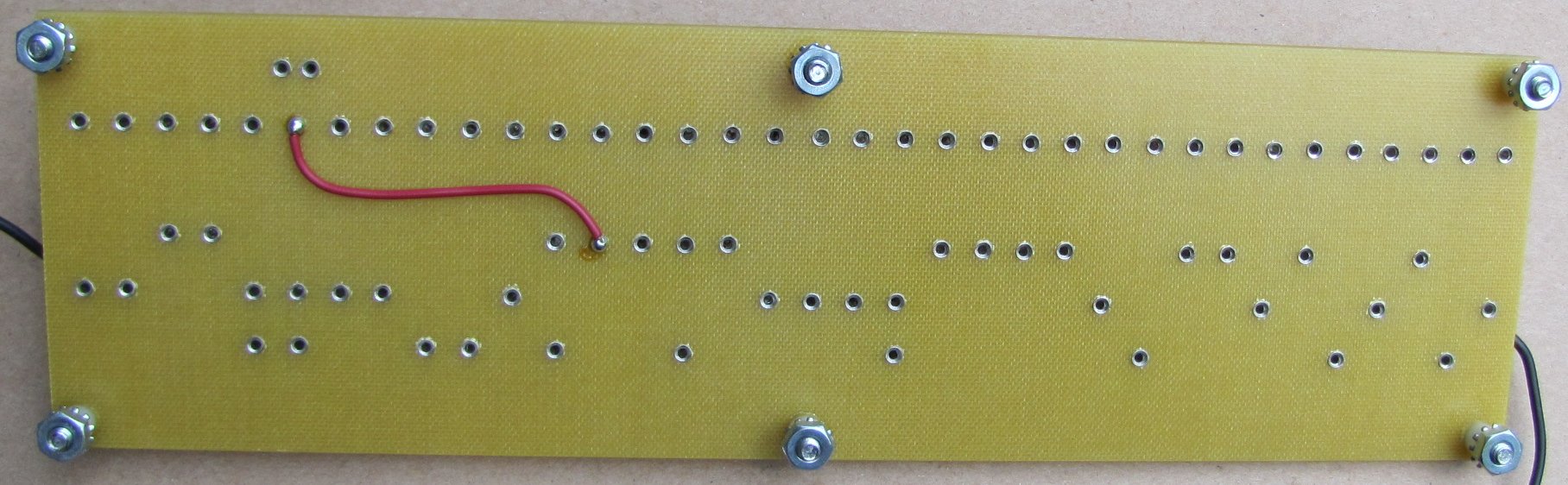 |
| Hoffman board info from the old web site. |
|
The boards shown on this page are all hand wired construction using turret lugs and 1/8 inch thick epoxy type circuit board. Carbon comp resistors and
polypropylene caps are standard. You can specify metal film resistors if you want. Some very large sized capacitors will not fit on the boards. For example a .1/600 volt Sprague
orange drop may be too large to use on a board. The fixed bias circuits all have a bias pot and one ohm resistors on the board so you can bias the amp yourself with a common multi
meter. Installation of a Hoffman board involves removing the old PC board from the amp, removing the old pots and input jacks if necessary. You then drill the new board mounting holes, bolt in the board and start wiring it up point to point. The actual manufacturing instructions for a Hoffman board are listed on the library page. |
|
If you purchase a Hoffman board and intend to install it yourself, the boards will come with additional items. Each board has different needs. For example, the reverb unit kit does not have 4 input jacks. |
| Items that come with a Hoffman Board |
| The Complete Circuit Board assembly, with all the ground wires, resistors, capacitors, bias pot, etc already mounted. Ready to bolt in and start wiring to all the tube sockets, pots, filter caps, etc. |
| Circuit board standoffs, mounting screws and nuts. |
| Quantity 4 of #12A Switchcraft input jacks. |
| Input jack resistors, quantity 4-68K and quantity 2 of the 1 MEG, half watt carbon. |
| Complete pot harness assembly with all pots joined with a buss wire soldered down the back and all jumper wires, caps, resistors soldered in place and ready to go. |
| Power tube input grid resistors for each power tube. Depending on the kit, usually 1.5k or 5.6k. |
| All hook up wire. |
| Mini shielded cable for the input jack to first pre amp tube connection. |
| Heat shrink tubing for the mini shielded cable. |
| Quantity 4 round ring terminals for making grounds to the chassis and power transformer. |
| Installation instructions and the layout diagram. |
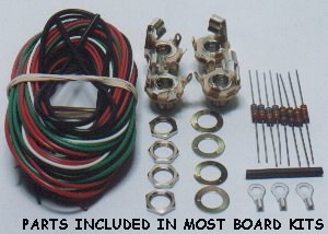 |
These are the assembly items that come with most of the Hoffman boards. Not all boards get the same items. You get several colors and gauges of wire. Some
mini shielded cable for the input jacks to the first tube. A piece of heat shrink tubing for the ends of the shielded cable. 4 x #12A Switchcraft input jacks. 4 x 68k and 2 x 1 meg
input jack resistors. 2 or 4 x 1.5k, 5.6k power tube control grid resistors. 4 round spade lugs for grounding wires to the chassis. The mounting hardware for the board includes the
standoffs, mounting screws and nuts. The Marshall boards come with tall standoffs so you can get over the top of the big cap under the board. The other boards come with 1/4"
nylon standoffs. The library page has links to the Instructions and layout diagrams that come with the boards below. |
 |
 |
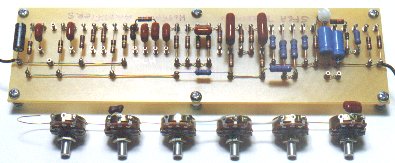
| 5F6A Bassman board | |
|
The 5F6A kit includes: The complete circuit board with all the parts mounted point to point using turret lugs. The board includes the bias pot and one ohm biasing resistors for each power tube. The ground wires are already connected to the board. Includes all mounting hardware and standoffs. Includes the complete pot harness assembly. Includes four #12A Switchcraft input jacks and all the input jack resistors. Includes all the hook up wire, shielded cable, heat shrink tubing and ring terminals. Board dimensions are 3.125 inches wide x 10.75 inches long. Installation instructions and the layout diagram. |
|
 |
|
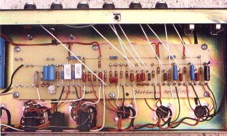
| Plexi board | |
|
The photo above shows the Plexi kit installed in a JTM 45 Bluesbreaker chassis. This chassis had a tube rectifier and only two big LCR filter
caps so I had to add an extra filter cap because the plexi circuit uses six filter caps. I highly recommend using this chassis because the voltages are lower than most other chassis
and the amp is not as aggressive and loud as most other chassis such as a JMP or JCM 800 chassis. NNote: JTM45's and Blues breaker's were the 5F6A Bassman circuit, not the later plexi circuit. I used the JTM45 chassis for a plexi board because it had a tube rectifier and the voltages that I was looking for. The kit includes:br> The complete circuit board with all the parts mounted point to point using turret lugs. The board includes the bias pot and one ohm biasing resistors for each power tube. The ground wires are already connected to the board. Includes all mounting hardware and standoffs. Includes the complete pot harness assembly. Includes four #12A Switchcraft input jacks and all the input jack resistors. Includes all the hook up wire, shielded cable, heat shrink tubing and ring terminals. Board dimensions are 3.125 inches wide x 11.25 inches long. Installation instructions and the layout diagram. |
|
 |
|
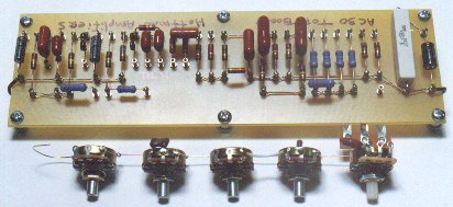
| Vox AC30 board | |
|
The AC30 kit does not include channel three, the tremolo channel. That channel requires three more 12AX7 tubes and as many parts as the main
amp, so the kit would be too large to fit in any amp carcass. The way that Vox did it on the old amps was to make two separate boards and place them 90 degrees to each other and
use tons of wire in a very rats nest fashion. The old amps are horrible to work on and a fire hazard but they have a very cool tone. Channel one on the kit is the regular no boost
channel and channel two is the cool top boost channel. Channel three the tremolo channel is not available. The kit includes: |
|
 |
|
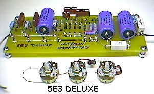
| 5E3 tweed Deluxe board | |
|
The kit includes: The complete circuit board with all the parts mounted point to point using turret lugs. The ground wires are already connected to the board. Includes all mounting hardware and standoffs. The power supply filter caps are already mounted on the main board. Includes the complete pot harness assembly. Includes four #12A Switchcraft input jacks and all the input jack resistors. Includes all the hook up wire, shielded cable, heat shrink tubing and ring terminals. Board dimensions are 3.125 inches wide x 8.25 inches long. Installation instructions and the layout diagram. |
|
 |
|
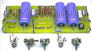
| 6G15 stand alone reverb board | |
|
Replace the PC board in the Fender re-issue stand alone reverb unit with a hand wired point to point board. The re-issue reverb unit uses a
bridge rectifier and this board kit is ready to go with a bridge mounted right on the main board.
The kit includes: |
|
 |
|
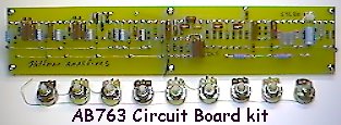
| AB763 board | |
|
The AB763 circuit is the Black face era Fender combo with reverb circuit that was used in the mid 1960's by fender. The same circuit was used on Deluxe reverb, Vibrolux Reverb, Super Reverb, Pro Reverb, Bandmaster Reverb, Vibroverb and Twin Reverbs. All of the chassis are different lengths on the models above. So you can see there is not just one chassis or model of AB763 circuit. Basically the only thing that makes any of those models different from the next is the transformer set and speakers. I have included the tremolo that was used on the 63-64
Vibroverb which does not uses an Optoisolator. The Vibroverb tremolo modulates the power tube bias voltage and is much smoother sounding than the Optoisolator tremolo. The pot assembly
comes with the mid range pots for both channels. You can remove the mid range pot and replace it with the 6.8K fixed mid range resistor that is included with the kit. This kit is
a monster to install because there are so many hook ups and I do not recommend you attempt it if you are not familiar with building an amp from scratch. I don't even like to do this
kit because it is so labor intensive. |
|
Enter My Tube Amp Parts Store Here
Mobile users Enter My Tube Amp Parts Store Here
The Tube amp Library of information
Click the link above for Tube amp info, Schematics, Board building information, Projects, Mods, Transformer diagrams, Photo's, Sound clips.
There are hundreds of pages of Tube amp information on my library page.
Please visit my Tube Amplifier Forum
Here's the place you can go to ask tube amplifier questions.
You will find a large community of friendly amp builders at the link above.
Check the huge library of Schematics here
Design your own custom Turret Board or Eyelet board
DIY Layout Creator file analyzer program
DIY Layout Creator file library
Sound clips and tunes of all types
How to email me
|
MEMBER OF PROJECT HONEY POT Spam Harvester Protection Network provided by Unspam |