
X10 project #2 |
| Back to main X10 projects page |
| - |
| This project will make a motion detector trigger a X10 Powerflash unit. The Powerflash then transmits an X-10 code on your house wiring. From there, you can do all sorts of things with X10 and this setup. |
| - |
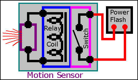 |
| Here's a diagram of how this project works The motion sensor senses motion and turns on a relay coil. The relay switch contacts close. The Powerflash contacts are then shorted or closed. The Powerflash transmits an X10 code. |
| - |
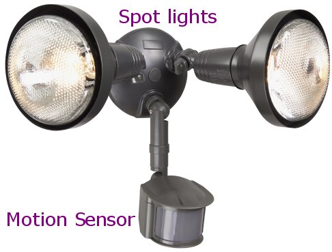
| The motion sensor board in the pictures below was part of a motion sensor dual spotlight assembly. The circuit board is powered by 120VAC from within the spotlight housing. The motion sensor board is made to turn on the two spot lights when motion is detected. The circuit board has a relay that turns on when motion is detected and sends 120VAC to the two spot lights via a simple spst relay. We are going to disconnect the 120VAC from the relay switch contacts and make the relay switch contacts trigger a X10 Powerflash unit. You cannot send 120VAC to the contacts of the Powerflash, we need to turn the relay into a simple switch with no voltages on the switch contacts. Fortunately it's very easy to get inside the motion detector unit and disconnect the 120 VAC from the relay switch contacts. We are going to slice a couple printed circuit board traces and interrupt the 120VAC from reaching the relay switch contacts. |
 |
| Once you cut off the 120VAC supply to the relay switch contacts, you end up with a simple set of switch points that open and close with no voltage on the relay switch contacts. The Powerflash unit has a mode that when the two contacts on the Powerflash are shorted out, it transmits an X10 signal onto your power lines and then all sorts of things are possible from there. The simple set of relay switch contacts can now trigger the Powerflash contacts. The Powerflash is set to Input B and Mode 3 |
| - |
| Click on images for larger image |
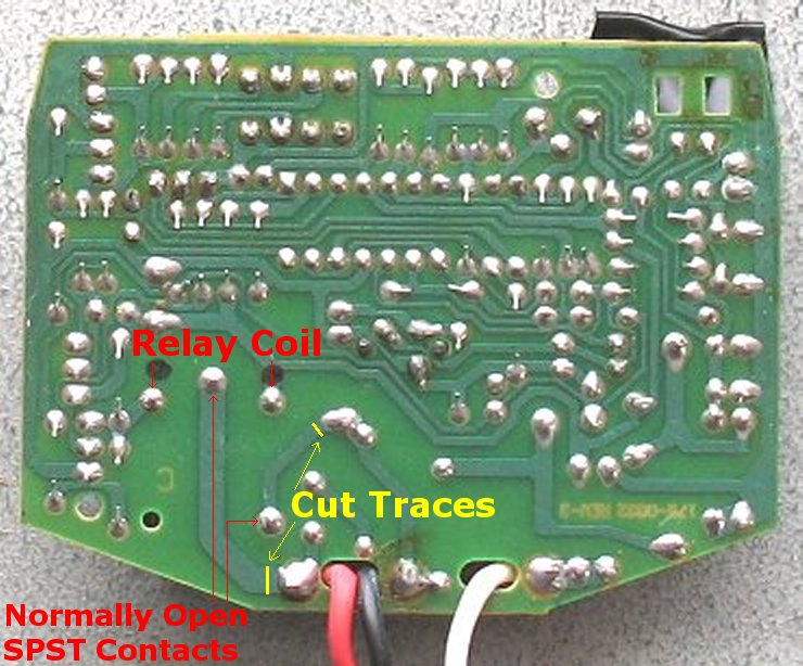 |
| The photo above shows the underside of the relay. You can see where the relay coil and relay switch connections are. It also shows where to cut through two circuit board traces. This disconnects 120VAC from reaching the relay switch contacts. The red wire in this picture will be removed also. |
| - |
| Click on images for larger image |
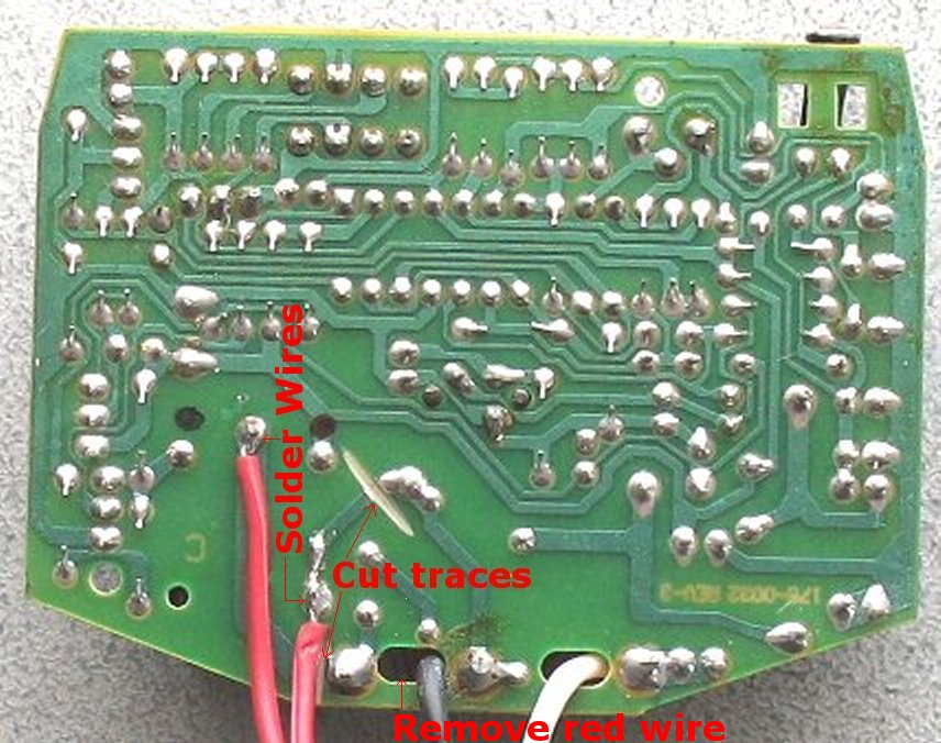 |
| In this photo, you can see that I have used a dremel tool to slice through the two circuit board traces. The lower cut is hidden under the red wire and hard to see but it looks just like the upper cut. Then I soldered two wires to the relay switch contact points. You can remove the red wire, it is not needed. The red wire is visible in the upper photo. You will be left with just a black and white wire to power the motion detector. |
| - |
| Click on images for larger image |
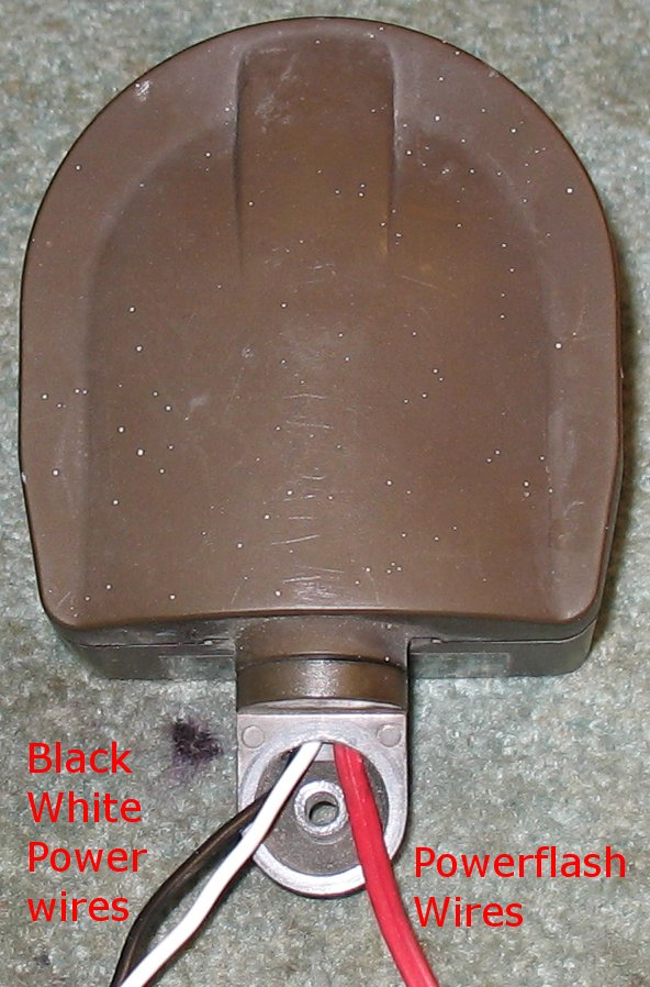 |
| Here you can see the motion detector re-assembled. The black and white are the power wires that get connected to 120VAC. The double red wires are the wires that get connected to the Powerflash unit. If you want to use the motion detector without spot lights, you will have to add a simple lamp cord/power cord to power the motion detector. If you want to re-attach the motion detector to the spot light assembly you will have to have the power flash near the spot lights or have a very long set of Powerflash wires. The spot lights could then be powered off and on when the Powerflash unit is triggered. The Powerflash unit can then trigger an X10 wall switch or appliance module that can then turn on the spot lights. All sort of possibilities are possible once the Powerflash unit is triggered. |
| - |
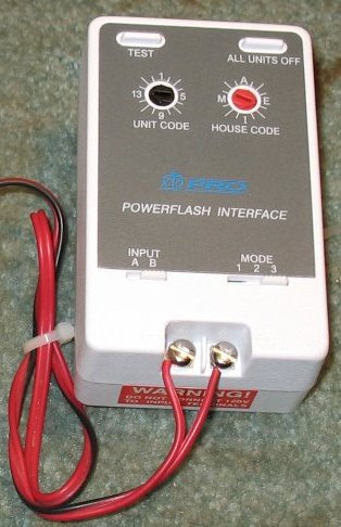 |
| Here you can see the double red wires connected to a Powerflash unit. The Powerflash is set to Input B and Mode 3 |
| - |
Enter My Tube Amp Parts Store Here
Mobile users Enter My Tube Amp Parts Store Here
The Tube amp Library of information
Click the link above for Tube amp info, Schematics, Board building information, Projects, Mods, Transformer diagrams, Photo's, Sound clips.
There are hundreds of pages of Tube amp information on my library page.
Please visit my Tube Amplifier Forum
Here's the place you can go to ask tube amplifier questions.
You will find a large community of friendly amp builders at the link above.
Check the huge library of Schematics here
Design your own custom Turret Board or Eyelet board
DIY Layout Creator file analyzer program
DIY Layout Creator file library
Sound clips and tunes of all types
How to email me
|
MEMBER OF PROJECT HONEY POT Spam Harvester Protection Network provided by Unspam |