
X10 project #1 |
|
| Back to main X10 projects page | |
| - | |
| This project will make a Radio frequency motion detector and base unit, trigger a X10 Powerflash unit. The Powerflash then transmits an X-10 code on your house wiring. From there, you can do all sorts of things with X10 and this setup. |
|
| - | |
 |
|
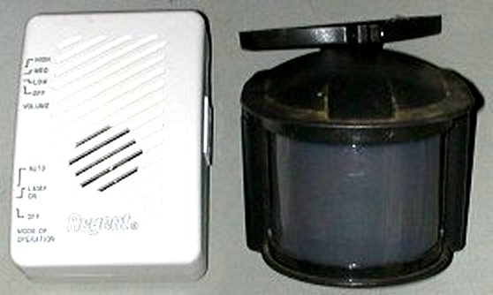
| This is the regent motion sensor and base unit combo that I bought at Lowes for around $30. It's actually a Cooper lighting product. I have seen
many Cooper lighting motion sensors on all kinds of motion products. The motion sensor is made for outdoor operation and easily picks up motion/heat 40ft away from the source. It's
much better at outdoor motion detection than the x-10 motion sensors I have. You can actually buy each unit above separately, but it's more expensive than buying both in a kit.
If you need to add multiple motion sensors on the same code to trigger one base unit, just buy more motion sensors separately. The motion sensor runs on 4 x AA batteries but I have converted mine to run on 5volt DC from a power source. I hate to change batteries and it's really rough on batteries to be outside in the cold weather. Murphy's law says that the batteries will go dead just when you need them. My experirnce with 3 of these units is that the batteries last a long time, 6 to 9 months if I remember correctly. The motion sensor and the base unit have 11 channels of radio frequencies that you can adjust with a rotary dial. You set the motion sensor and the base unit to the same channel. In normal operation, the base unit receives a radio signal from the motion sensor and then can turn on a lamp and/or ring a chime. I have 3 of these units on my property, all set to different channels so they do not interfere with each other. My neighbor also has one and we agreed on the channels we would each use. He's really not close enough to me to set off my base units but we picked our channels anyway. The base unit has two slide switches. You can set one switch to chime when motion is detected. The four switch settings are volume level High-Med-Low-Off (no chime). The other switch controls the lamp socket output on the side of the unit. You can set this switch to Auto (Lamp on and off with motion) - Lamp on (lamp on full time) - Off (lamp never on) |
|
| - | |
 |
|
| Here's a diagram of how this project works The motion sensor transmits a signal to the base unit when the motion sensor detects motion. The base unit turns on a relay coil. The base unit relay switch contacts close. The Powerflash contacts are then shorted or closed. The Powerflash transmits an X10 code. |
|
| - | |
 |
|
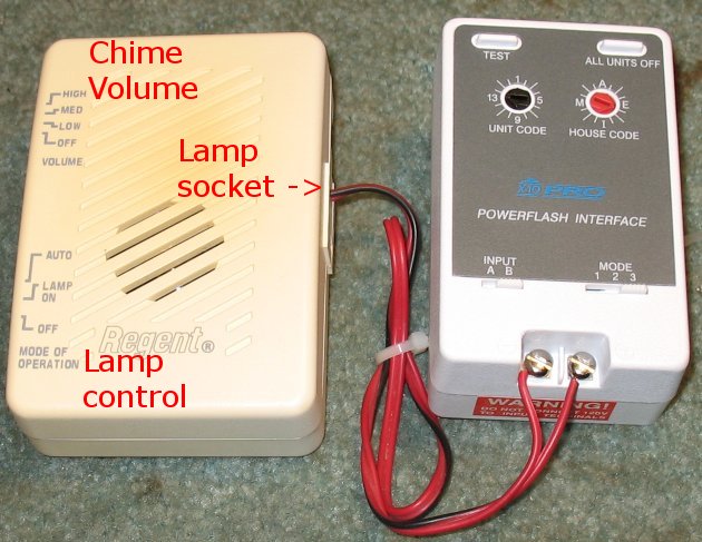
| The base unit on the left triggers the Powerflash on the right. The Powerflash is set to Input B and Mode 3. | |
| The motion detector base unit normally turns on and off a lamp socket when the motion detector unit is triggered. The lamp socket is turning on
and off 120 volts AC. You cannot send 120 volts AC to the contacts of a Powerflash unit. Fortunately it's very easy to get inside the base unit and disconnect the 120 VAC from the
relay switch contacts/lamp socket out. The base unit has a relay inside that is turning on and off the 120VAC to the lamp socket. We are going to slice a printed circuit board trace and interrupt the 120VAC from reaching the relay switch contacts. There is also one small feedback resistor that we are going to unsolder one end on, because it feeds back 120VAC from a 120VAC contact point. Once you cut off the 120VAC supply to the relay switch contacts, you end up with a simple set of switch points that open and close with no voltage on the relay switch contacts. The Powerflash unit has a mode that when the two contacts on the Powerflash are shorted out, it transmits an X10 signal onto your power lines and then all sorts of things are possible from there. The simple set of relay switch contacts can now trigger the Powerflash contacts. The Powerflash is set to Input B and Mode 3 I will also be removing the two female lamp socket plugs from the printed circuit board so that nothing can be plugged into them. There is still 120VAC going to these female jacks and so it's best to get rid of them for safety. I am using the lamp socket hole as an exit for my switch contact wires that go to the Powerflash unit. I'll probably forget 5 years from now why I can't plug anything into the base unit lamp socket. Having the wire sticking out of one hole may remind me. Removing the female jacks prevents me. :) |
|
| Click on images for larger image | Click on images for larger image |
 |
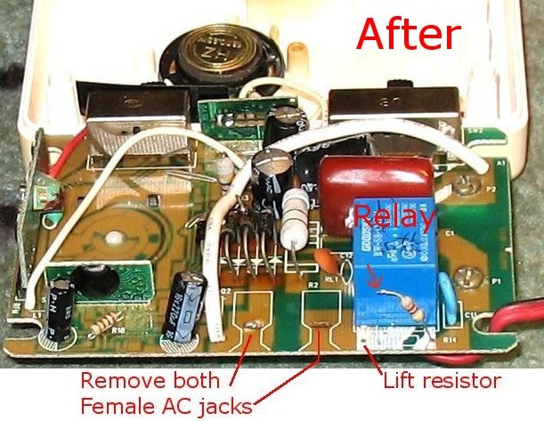 |
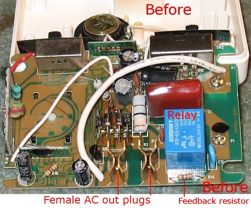
| Before shot of the unaltered insides | I removed the Female Ac out jacks and unsoldered one end of the feedback resistor so that 120vac is removed completely from the relay out contacts. A trace on the backside of the board still needs to be cut. |
| Click on images for larger image | Click on images for larger image |
 |
 |
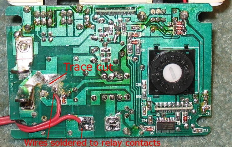
| I cut the trace that was sending 120VAC to the relay contact points and then soldered two wires to the relay switch contact points. |
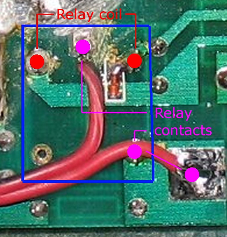
Close up of back of relay. Red dots are the relay coil. The fuscia dots are the relay switch contacts. I soldered two wires to the relay switch contact points. These wires will go to the Powerflash contacts. |
| - | - |
Enter My Tube Amp Parts Store Here
Mobile users Enter My Tube Amp Parts Store Here
The Tube amp Library of information
Click the link above for Tube amp info, Schematics, Board building information, Projects, Mods, Transformer diagrams, Photo's, Sound clips.
There are hundreds of pages of Tube amp information on my library page.
Please visit my Tube Amplifier Forum
Here's the place you can go to ask tube amplifier questions.
You will find a large community of friendly amp builders at the link above.
Check the huge library of Schematics here
Design your own custom Turret Board or Eyelet board
DIY Layout Creator file analyzer program
DIY Layout Creator file library
Sound clips and tunes of all types
How to email me
|
MEMBER OF PROJECT HONEY POT Spam Harvester Protection Network provided by Unspam |