
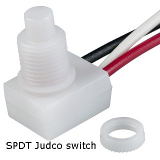
Judco switch and two 1400ma current limiter boards
|

| Click on Image below for a larger Image |
 |
|
This diagram describes the SPDT Judco switch switching and how it works with the dual 1400ma current limiter boards. OFF - When the switch is off, the battery negative is disconnected from both boards and so the LED is off LOW MODE - When the switch is on the Low mode, it connects the battery negative to one 1400ma current limiter board. This limits the LED current to 1400ma giving you a low power mode. High MODE - When the switch is on the High mode, it connects the battery negative to both 1400ma current limiter boards This limits the LED current to 2800ma giving you a High power mode. Note that the SPDT Judco switch actually has 4 click positions. (OFF) - (ON1 = low) - (ON1 & ON 2 = High) - (ON2 = low) There are actually two low modes and one high mode because of the way this switch works internally Each low mode just turns on one board. They are both the same, 1400ma of current limiting |
|
Assembly Notes: This mod is almost exactly like my first clicky switch mod that used these current limiting boards. The only difference is that this mod uses the Judco switch that switches things just a bit differently as noted above. The Judco switches are USA made push button switches that are very high quality. I am using Rubber switch boots that waterproof the switch plunger on the Judco switches You do not have to solder the jumper wire across the diodes. I do it because I do not trust the tiny surface mount diodes. If a diode fails, two 7135 chips will turn off and you will loose 700 milliamps of current regulation. Each 7135 chip regulates 350 milliamps of current and each diode feeds two 7135 chips. The diodes are on the boards for protection in case you hook up your battery backwards. The 3.6 volts Battery + voltage comes down the center wire, goes through the diodes and supplies the 3.6 volts to the chips. If you think it is possible that you may install a battery backwards, it may be advisable to not jumper across the diodes. I use soldered together battery packs and so it is impossible for me to hook up my batteries backwards. Some people use battery packs with removable batteries and it is possible to install your batteries backwards in a battery holder. The two bare wires that I add to the switch supply the 3.6 volts battery negative voltage to the current regulator boards. When both boards are on, they are in parallel. All 8 of the 7135 chips regulate 350 milliamps each x 8 = 2800 milliamps total. I am using the stock Marwi rear plastic housing for this mod because the Judco switch has a much smaller hole size than the clicky switch tail cap mod. The Marwi halogen lights originally came with a SPST Judco switch that has the same diameter hole as the SPDT Judco switch I am using. |
| Click on the images for a larger image | |
 |
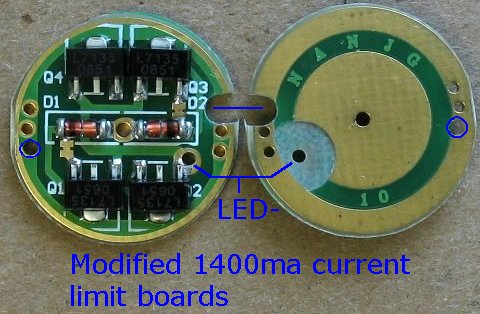 |
| This is the Judco SPDT switch | These are the CNC machine modified 1400ma current limiter boards |
| - | |
| Click on the images for a larger image | |
 |
 |
|
Space is tight inside the Marwi housing and so I needed to reduce the size of the 18 gauge stranded black and red switch wires. These two wires go to the ground/negative holes on each current limiter board and cannot be a large diameter wire. I first snip the wires short and tin the wires with solder I then add some 20 gauge solid core buss wire to each 18 gauge wire. |
|
| - | |
| Click on the images for a larger image | |
 |
 |
|
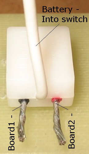
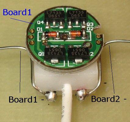
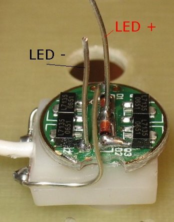
I snip off the extra 18 gauge wire lengths and bend the two 20 gauge wires around the switch body Board #1 is glued to the back of the switch to hold it in place |
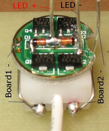
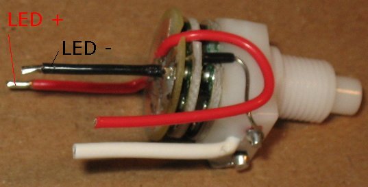
I add a LED + wire and a LED - wire to board #1 I also solder a jumper wire across the length of both diodes to bypass the diodes There is better picture down below that shows this jumper wire. Both boards get the same jumper wire treatment |
| - | |
| Click on the images for a larger image | |
 |
 |
|
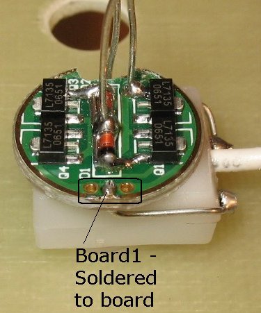
View from side #1 One 20 gauge wire is soldered to board #1 ground/negative |
View from side #2 The other 20 gauge wire must pass through board #1 on it's way to board #2. I have widened the notch a bit on board#1 with a Dremel tool |
| - | |
| Click on the images for a larger image | |
 |
 |
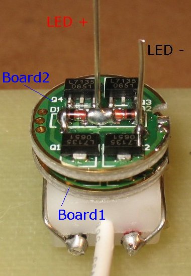
| Board #2 slides down onto the LED+ and LED- wires |
The other 20 gauge solid core wire is soldered to board #2 ground/negative. I added a bit of wire insulation to the bare wire so that it does not short out on board #1 You can see the jumper wire across the back of the diodes better in this picture Both boards get the same jumper wire treatment |
| - | |
| Click on the images for a larger image | |
 |
 |
|
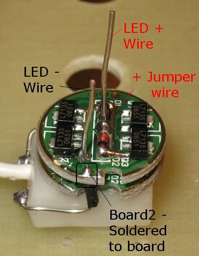
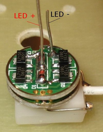
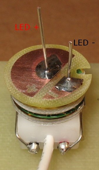
Another view of board #2 sitting on top of board #1 The LED+ and LED- wires have been soldered. The diode jumper wire has been soldered in place |
The LED hookup board is slid down onto the LED+ and LED- wires. This board keeps everything centered when inside the heat sink. It also is the connection point for several solder connections |
| - | |
| Click on the images for a larger image | |
 |
 |
|
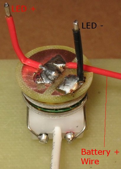
I have soldered 3 wires to the LED hookup board. The short Red LED+ wire and the Black LED- wire. I have also soldered a longer Red Battery+ wire. The battery+ wire fits down into the notch so that the heat sink can slide down onto the whole stack. |
|
| - | |
| Click on the images for a larger image | |
 |
 |
|
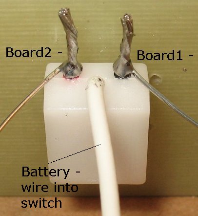
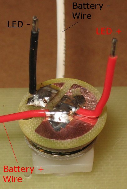
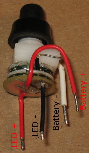
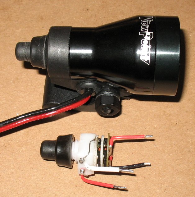
Here are two different views of the completed assembly. The Red LED+ wire goes to the LED+ connection point The Black LED- wire goes to the LED- connection point The White Battery- wire goes to the battery pack minus wire The Red Battery+ wire goes to the battery pack plus wire Note that this whole assembly fits inside the rear Marwi plastic housing. The 20 gauge solid core wires do not need to be insulated because there is nothing inside the housing that can short out these wires. The 20 gauge solid core wires hug the body of the switch tightly and stays out of harms way. |
|
| - | |
| Click on the images for a larger image | |
 |
 |
|
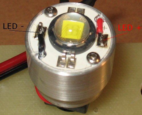
Next I slide the heat sink/LED down onto the stack The Red and Black LED wires come up through holes in the heat sink. I bend over the wires and solder them to the LED + and - connection points. Note that the LED has thermal grease under it and it is screwed down to the heat sink |
I will have to post a picture later of how I hook up the battery pack Red and Black wires. Here's the basics Shove the Red/Back battery pack wire through the grommet on the Marwi housing The battery pack Red wire gets soldered to the Red wire on the switch assembly The battery pack Black wire gets soldered to the white wire on the switch assembly. I dab a bit of super glue on both solder joints and then slide on a couple short pieces of heat shrink. I then shrink down the heat shrink tubing. I push the switch through the rear housing and thread on the rubber boot. I use a small dental pick to push the wires around into a good location as I do all that. |
| - | |
| Click on the images for a larger image | |
 |
|
|
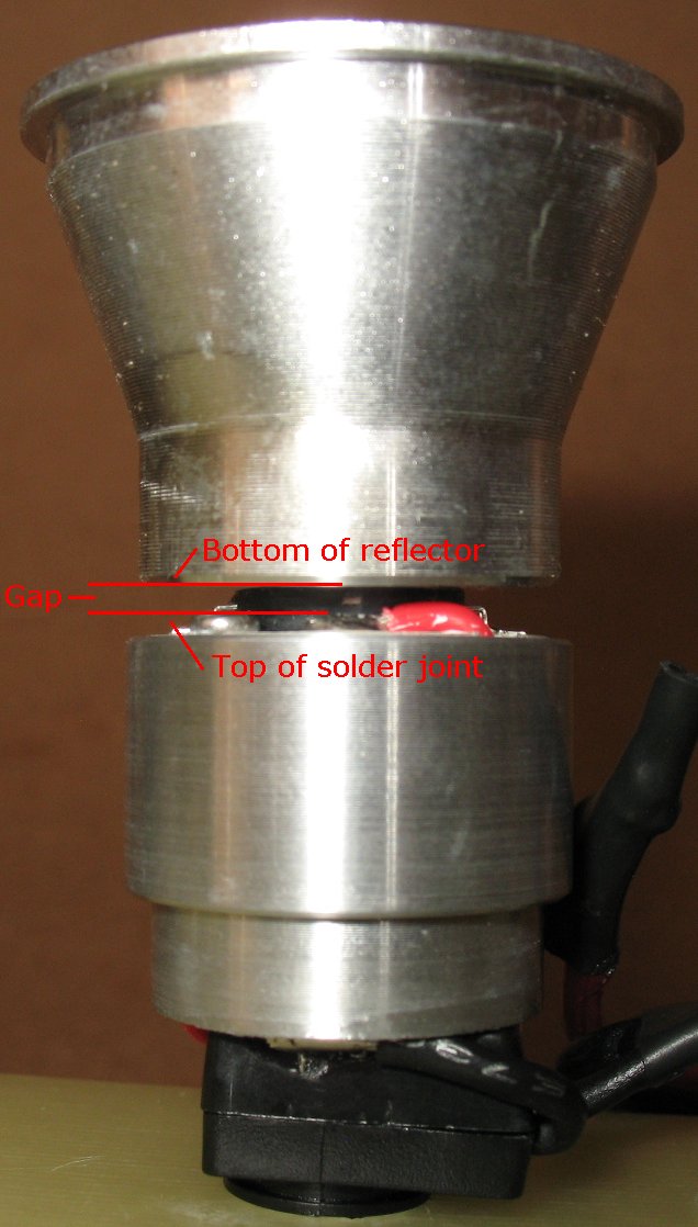
This picture illustrates how important it is to keep your solder joints as low as possible when soldering the LED + and - wires to the led connection
points. If you blob a bunch of solder onto the solder joints, and the solder joints stick up too high, it is possible to short out the LED connections on the rear of the reflector. We are working with a very low voltage (3.6 volts DC) and so arcing across the gap is not really an issue like it would be in a high voltage application. I machine the LED hole in the reflectors to fit very snugly around the LED. The LED has a hard black ring around the soft lens material. The reflector sits on that hard black ring. When the reflector is inside the Marwi body, it fits snugly and will not rock sideways and short out the connections. The heat sink slides into the body very snugly also and it will not rock sideways. The reflector and the heat sink stay in perfect alignment inside the Marwi body. Still, you must have good soldering technique when soldering the LED connections. |
|
| - | |
Enter My Tube Amp Parts Store Here
Mobile users Enter My Tube Amp Parts Store Here
The Tube amp Library of information
Click the link above for Tube amp info, Schematics, Board building information, Projects, Mods, Transformer diagrams, Photo's, Sound clips.
There are hundreds of pages of Tube amp information on my library page.
Please visit my Tube Amplifier Forum
Here's the place you can go to ask tube amplifier questions.
You will find a large community of friendly amp builders at the link above.
Check the huge library of Schematics here
Design your own custom Turret Board or Eyelet board
DIY Layout Creator file analyzer program
DIY Layout Creator file library
Sound clips and tunes of all types
How to email me
|
MEMBER OF PROJECT HONEY POT Spam Harvester Protection Network provided by Unspam |