
Dual 1400ma current limiter boards with clicky switch - Version 3 |
|
| - | |
| Click on the images for a larger image | |
 |
|
|
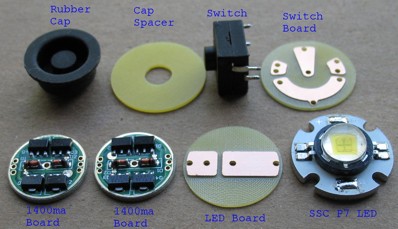
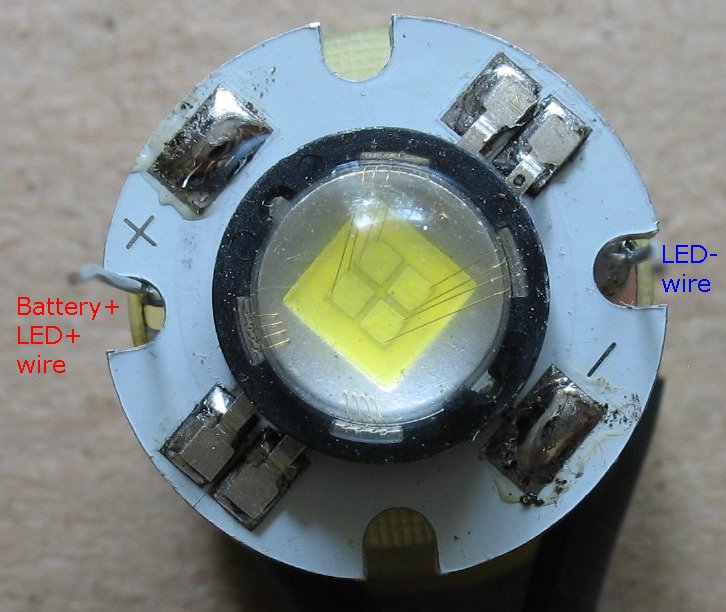
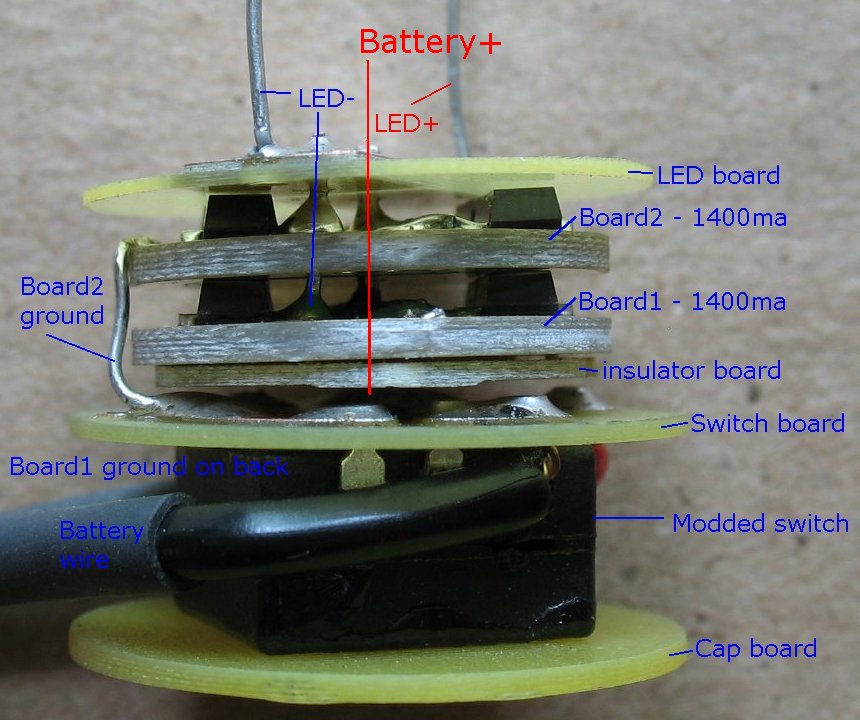
These are all the items inside my SSC P7 electronics stack. This process is still in the development stage. I keep finding cooler ways to create a 1400ma/2800ma current limiter for the SSC P7 LED |
|
|
Update: The cap spacer shown above has now been replaced by the spacer below that has solder points for the Battery+ and Battery-. I did that because it was too difficult to unsolder the battery hookup wires once the whole stack was soldered together. |
|
| - | |
| Click on the images for a larger image | |
 |
 |
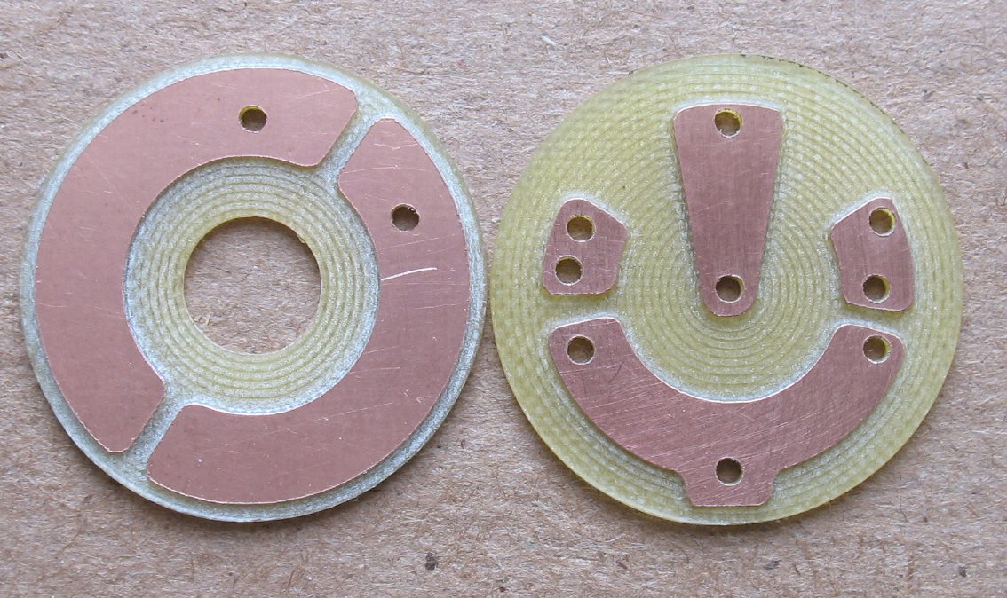
| Here's an updated photo of the two boards that go on either side of the switch |
I made it so you can jumper two large buss wires from one board to the other. This gives you a nice solid place to solder the battery + and - |
| - | |
| Click on the images for a larger image | |
 |
 |
|
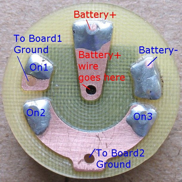
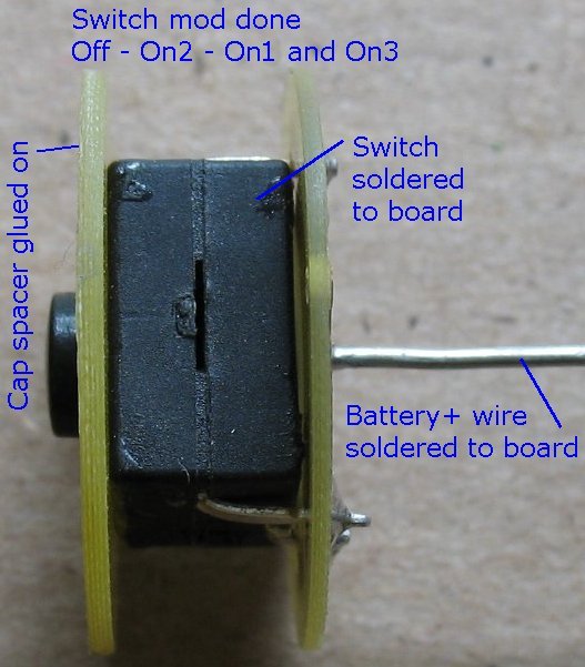
The switch board on2 connects the battery- to board two and gives you 1400ma current limiting on1 connects the battery- to board one and gives you 2800ma current limiting on3 passes the battery- to on1, and so both boards are now on at the same time |
Cap spacer - switch - switch board The center battery+ wire has been added to the switch board |
| - | |
| Click on the images for a larger image | |
 |
 - - |
|
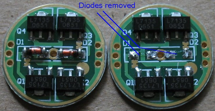
1400ma current limiter boards with the diodes removed on the right board Both boards get the diodes removed |
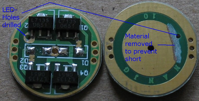
Holes drilled in both boards for the LED- wire to pass through. The LED- wire gets soldered and passes through boards two and the LED board |
| - | |
| Click on the images for a larger image | |
 |
 |
|
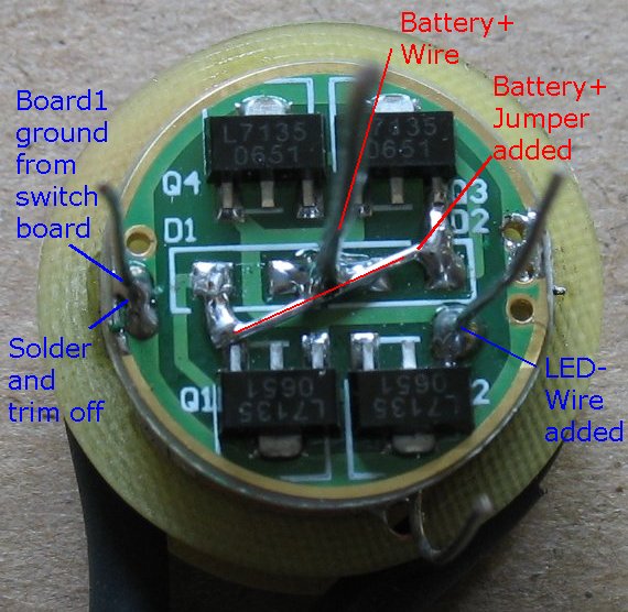
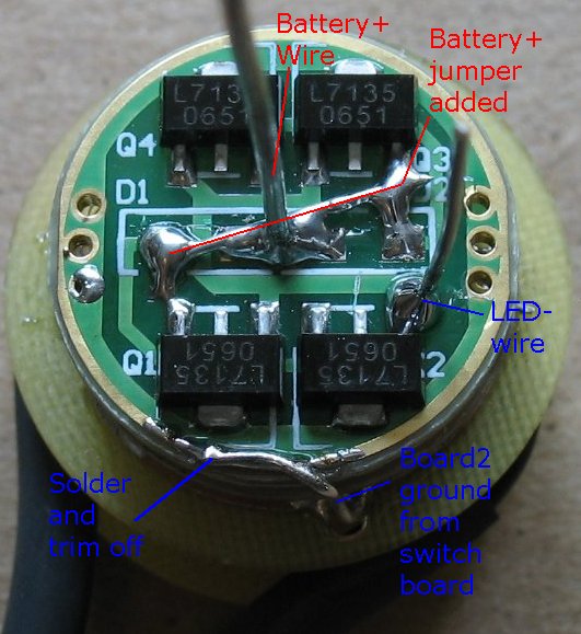
One 1400ma board has been added to the stack The whole stack is centered on the Battery+ wire A battery+ jumper wire is added to the board The negative for board one comes from the switch The LED- wire gets soldered and passes through to board two |
The second 1400ma board is added to the stack A battery+ jumper wire is added to the board The negative for board two comes from the switch The LED- wire gets soldered and passes through to the LED board |
| - | |
| Click on the images for a larger image | |
 |
 |
|
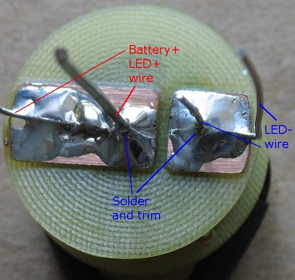
The LED board gets added to the stack The battery+ wire gets soldered and trimmed off The LED- wire gets soldered and trimmed off LED+ and LED- wires get added towards the outside of the board |
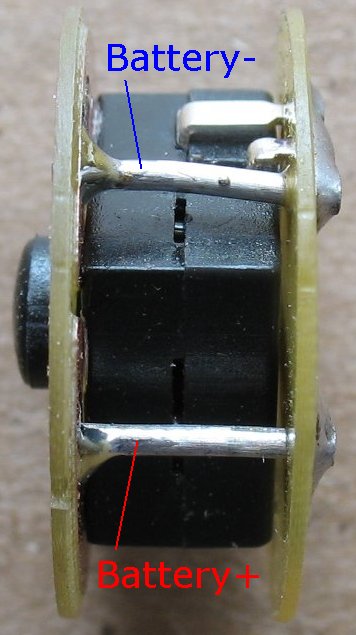
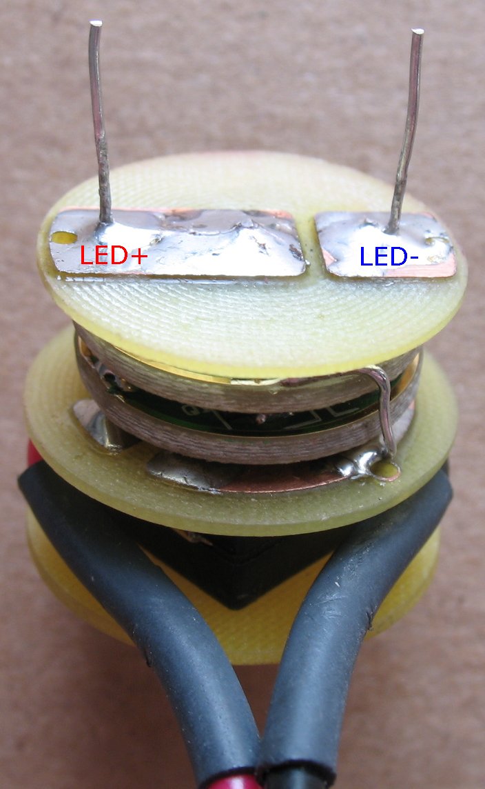
Side view of the stack LED+ and LED- wires get added towards the outside of the board
|
| - | |
| Click on the images for a larger image | |
 |
- |
|
LED+ and LED- wires from the board below come up through the + and - holes. A bit of heat shrink or wire jacket gets put around the + and - to keep them from shorting out. |
- |
| - | |
| Click on the images for a larger image | |
 |
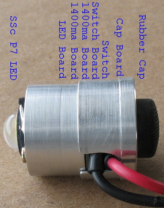 - - |
| Here's the stack without the LED |
The whole stack goes inside this assembly. This assembly fits snug into the main body |
| - | |
Enter My Tube Amp Parts Store Here
Mobile users Enter My Tube Amp Parts Store Here
The Tube amp Library of information
Click the link above for Tube amp info, Schematics, Board building information, Projects, Mods, Transformer diagrams, Photo's, Sound clips.
There are hundreds of pages of Tube amp information on my library page.
Please visit my Tube Amplifier Forum
Here's the place you can go to ask tube amplifier questions.
You will find a large community of friendly amp builders at the link above.
Check the huge library of Schematics here
Design your own custom Turret Board or Eyelet board
DIY Layout Creator file analyzer program
DIY Layout Creator file library
Sound clips and tunes of all types
How to email me
|
MEMBER OF PROJECT HONEY POT Spam Harvester Protection Network provided by Unspam |