
| Back to Library page | |
MY USB footswitch controller |
|
| - | |
| This page shows how to hack a USB keyboard and turn it into a USB footswitch. Here's a short movie showing how my switching experiment works with Mixcraft This is the first PS2 keyboard experiment https://el34world.com/Misc/Movies/MX5.wmv I am using this footswitch to send a string of keyboard commands to my recording software. The footswitch triggers a keyboard character and then I have a program that intercepts that character and then triggers a macro of many keyboard commands This lets you set up a very complex sequence of events with just one keyboard character. This is not Midi, it is taking advantage of all the things you can do via keyboard commands, only you can do them with your feet. I am using a USB keyboard because I want to be able to plug it in on the fly, which you can do with USB devices. I tested this footswitch idea using a PS2 keyboard, and it worked fine also. You don't have to make a USB footswitch from scratch, they actually sell them Note that in most cases, you would want one that you can program the keys that are triggered You would not want one that is limited to only certain keys because those keys are used in normal program typing Here's a web page that has many different styles of USB footswitches http://www.delcomproducts.com/products_usbfsw.asp They also sell USB controller boards for use in home made arcade type games These boards are supposedly way better quality than a cheapo USB keyboard like I am using. From what I have read, the arcade type boards are able to generate many keyboard commands at one time Joysticks and arcade games may have many keys pressed at the same time during game play. A USB keyboard is only able to do 6 keys at one time which is way more than I need |
|
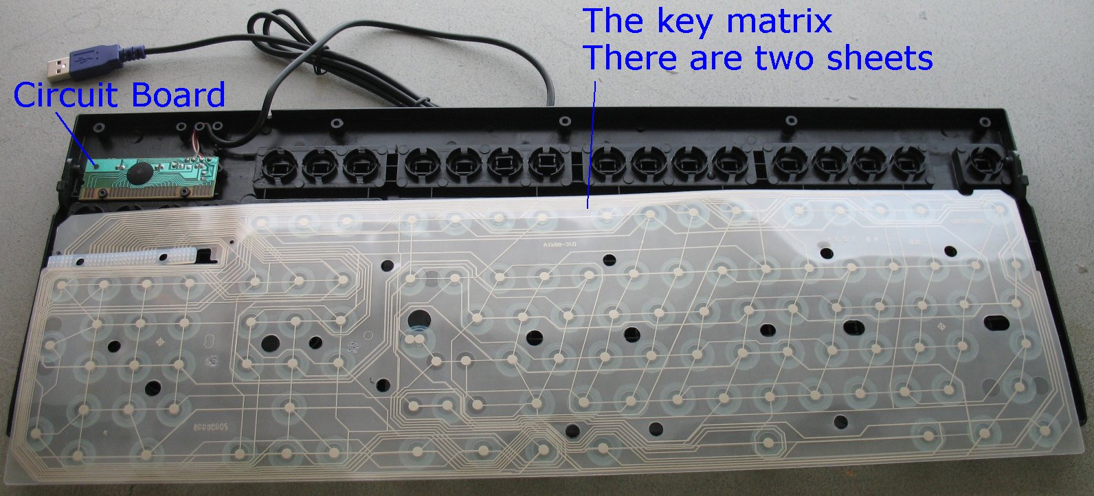
Here's how the basic modern keyboard works. There are three plastic sheets that are tacked together with spot welds The upper and lower sheets have carbon traces and the middle sheet is just a plain clear sheet with no carbon traces The carbon traces conduct electric current. The middle clear sheet is just an insulator to keep the two sheets from touching until you press a key. When you press down on a key you are pressing the two sheets that have carbon traces together to make a switch connection. The middle sheet has holes everywhere there is a keyboard switch so it does not get in the way when you press the upper and lower sheets together. Once you press a key, the circuit board figures out what key was pressed and then sends that info to the computer. There is a computer chip on the circuit board that handles all that complex stuff. The two sheets that have the carbon traces have very small traces that lead back to the circuit board. So, you can duplicate a key being pressed if you find the spot on the plastic sheets and follow the traces back to the circuit board. Then all you do it solder tiny wires to the circuit board and use foot switches to simulate pressing a key down on the keyboard. It's way easier to understand if you take a keyboard apart and study it. Don't take your favorite keyboard apart, you make never get it back together and working again. There's a ton of small parts that can fly out and be impossible to reconstruct back into a working keyboard. This page has some info regarding keyboard hacks http://www.instructables.com/id/Hacking-a-USB-Keyboard/ Also, you can do a Google search for keyboard hacks and find lots of info. Seems that it is very popular thing to do. People are using keyboard hacks to make home made arcade game controllers. |
|
This is the program that I run in the system tray that triggers the macro's http://www.autohotkey.com/ What you do is take the stock config file called AutoHotkey.ahk and alter it to suit your needs. You will have to download it and read the help file to get a better idea of how the whole thing works. It's a great little free program that can do many things. The Auto Hot Key code I am using for my particular footswitch needs is shown below |
|
The ^ character shown below is a shortcut for the Control key So ^r is Control + R The ; character is a comment line, everything after the ; is ignored The code below is simple, it just starts and stops recording when I press the [ key ; Mixcraft - Start and Stop recording [:: Send, ^r return This bit of code is a bit more complex and does many things All of the items in this sequence are keyboard shortcuts in Mixcraft When I press the ] character the macro below will execute and Mixcraft will execute each keyboard command in the macro ; Mixcraft rewind sequence ]:: Send, ^g ;Add a new audio track Sleep, 100 Send, {DOWN} ;Move the clip down to the new track Sleep, 100 Send, ^u ;move the selected track up one Sleep, 100 Send, {ESC} ;un-highlight the clip Sleep, 100 Send, ^m ; mute the track you just recorded ; The sequence below rewinds to the last marker flag and then stops Sleep, 100 Send, {SHIFTDOWN}{CTRLDOWN}{SPACE}{SHIFTUP}{CTRLUP} Send, {SPACE} return |
|
| - | |
| Click on images to see a larger image | |
 |
 |
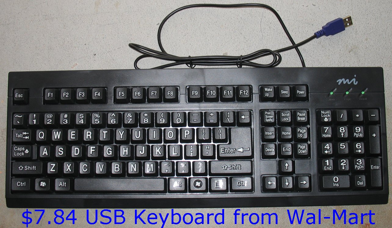
| Here's my victim, a $7.84 USB keyboard from Wal-Mart. How can they make and sell something this complex for that cheap? |
The inside of the keyboard. The circuit board is on the upper left. The clear sheets have been pulled forward. |
| - | |
| Click on images to see a larger image | |
 |
 |
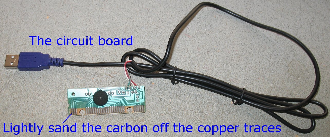
| Here's the guts of the whole thing. These are the only parts we will use. The circuit board and the USB cable |
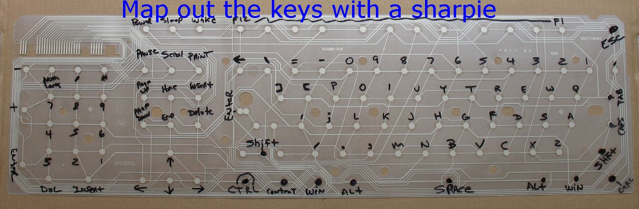
Lay the sheets back on the keyboard and map out the keys with a sharpie You don't have to do them all, only the keys you are interested in. |
| The electrical connection between the clear sheets and the circuit board is only a press fit. The circuit board has copper traces, but the traces are coated with some sort of carbon dust. When you press the carbon traces on the circuit board up against the carbon traces on the sheets, they make the electrical contact. You have to lightly sand the carbon dust off the copper traces in order to be able to solder wires to the copper traces. I have seen other keyboard hack web sites where they have just glued wires to the carbon dust and not removed it. |
|
| - | |
| Click on images to see a larger image | |
 |
|
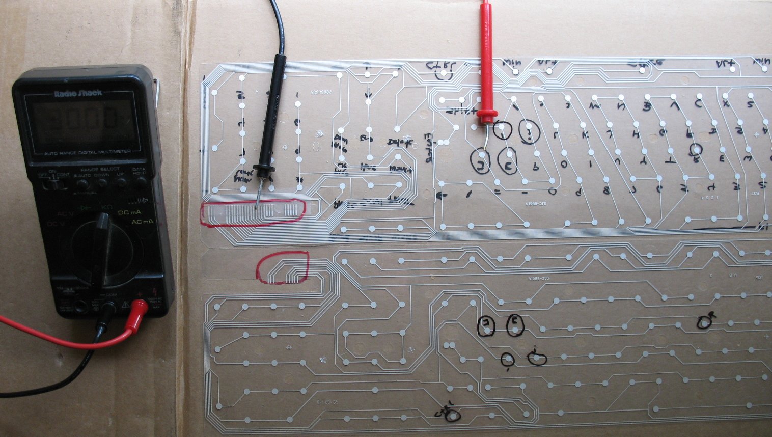
| Split the spot welded sheets apart carefully. Don't rip the plastic sheets apart and break any of the traces I have the sheets laid out like an open book here. Only one side of each sheet has the carbon traces. You can use a multimeter set to continuity-Beep to trace the round key pads back to the area that contacts the circuit board traces. It's a whole lot easier with a meter that beeps. If you don't have a meter that beeps, you will have to follow the small traces back manually. When you press a key, the two sheets come together to make a connection. For every key pressed, you have to trace two connections back to the circuit board, one from each sheet. The red circled area on the upper left is the area that contacts the circuit board traces. Count over from left to right the number of traces and make note of that for each key you want to use. On my project I am only using the [ and ] keys. The [ key mapped out to #14 and #20 on the circuit board traces The ] key mapped out to #7 and #20 on the circuit board traces So, if I solder a wire to #14 and #20 and I touch those wires together, it will trigger the [ key. The key mapping is going to be different for every type of keyboard, so my map above is no good for other keyboards. You will have to map out your particular keyboard. |
|
| - | |
| Click on images to see a larger image | |
 |
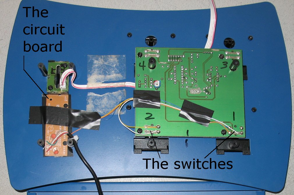 |
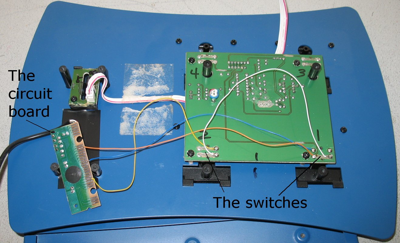
| Here's the inside of the foot switch unit I am going to use. | Another shot with everything tapped down and the wire secured |
| On the left above you can see that I have soldered tiny wires to the #7, #14 and #20 copper traces The lower end of the circuit board is trace #1 and the upper end is trace #26 The blue and orange wires will trigger a [ character when I step on a switch and connect those two wires The yellow and orange wires will trigger a ] character when I step on a switch and connect those two wires Both of those characters will set off a macro consisting of multiple keyboard commands |
|
| - | |
| Click on images to see a larger image | |
 |
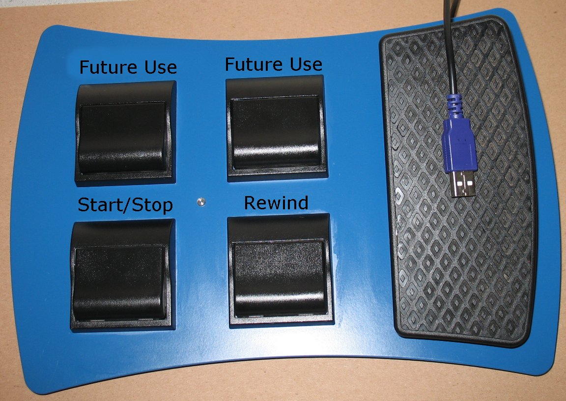 |
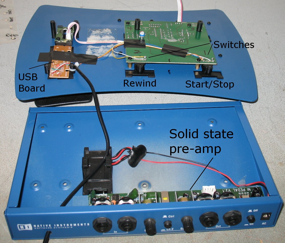
| The controller I am using here is the Rig Kontrol from Guitar Rig #1 It's not usable in later version of Guitar rig and so it's now my experiment There's a solid state pre-amp inside that still works if I ever needed that. |
Here's the controller all assembled with the two switches I am using I have two more switches for future use. |
| - | |
Enter My Tube Amp Parts Store Here
Mobile users Enter My Tube Amp Parts Store Here
The Tube amp Library of information
Click the link above for Tube amp info, Schematics, Board building information, Projects, Mods, Transformer diagrams, Photo's, Sound clips.
There are hundreds of pages of Tube amp information on my library page.
Please visit my Tube Amplifier Forum
Here's the place you can go to ask tube amplifier questions.
You will find a large community of friendly amp builders at the link above.
Check the huge library of Schematics here
Design your own custom Turret Board or Eyelet board
DIY Layout Creator file analyzer program
DIY Layout Creator file library
Sound clips and tunes of all types
How to email me
|
MEMBER OF PROJECT HONEY POT Spam Harvester Protection Network provided by Unspam |