
EL34's CNC Stuff - New CNC Machine |
|
| Back to main CNC page | |
| - | |
| 01/31/2008 - Added Y and Z axis limit sitches and limit switch adjustment screws. | |
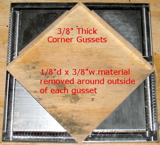
| 01/30/2008 - Cut out the corner gussets - added X axis limit switches | |
| 01/29/2008 - Added Y axis upright bracing. Made long motor mount screws. Drilled holes all over the frame to mount the top to. Made the X axis bearing block of oak for now until I can come up with a better design. | |
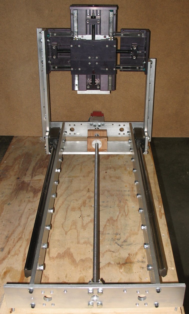
| 01/16/2008 - I cut the bottom piece that connects the two Y axis uprights. The X axis screw block/Delrin bearings holder will connect to this piece. Note that I can go to twin screws in the future if I want to. I still have to add some corners gussets and cross bracing to the frame before I have it all welded solid. I plan on adding some 1" Angle aluminum pieces to the Y axis uprights to give them more side to side rigidity. | |
| Click on the images to see a larger image | |
 |
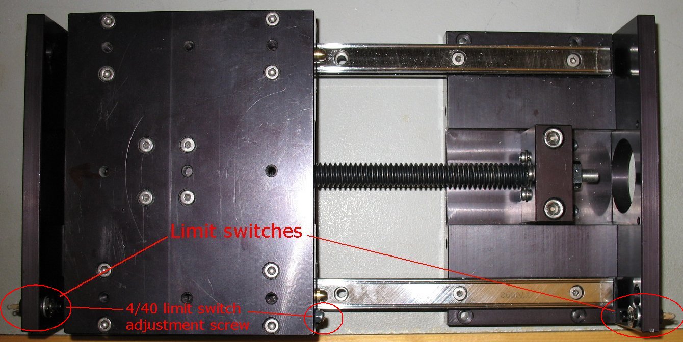 |
| Work in progress | Added limit switches to the Y axis THK FGS200 and Z axis THK FGS 140 |
| - | |
| Click on the images to see a larger image | |
 |
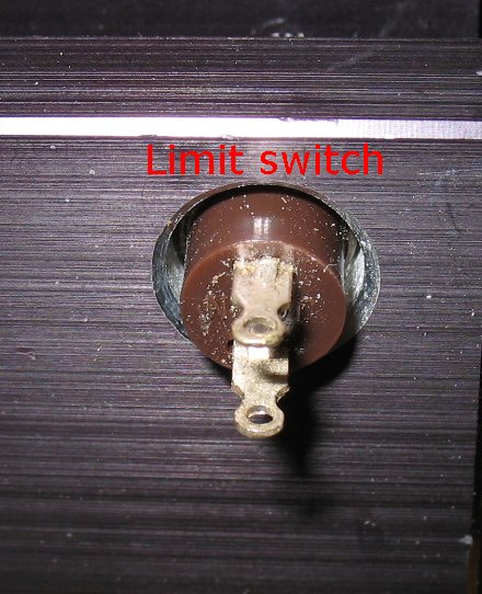 |
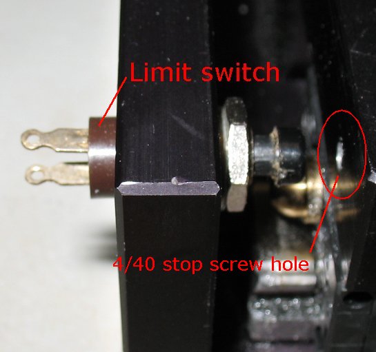
| Limit switches - I drilled and tapped small 4/40 adjustment screws where the tip of the limit switches contacts the sliding platform on the actuators. I can move the screw heads in and out to adjust the limit switch contact points. The 4/40 screws have nuts on them so I can lock the screw position. The picture on the left above does not have the screw in the hole yet. You can see one of the screw heads in the large actuator photo above on the right. | |
| - | |
| Click on the images to see a larger image | |
 |
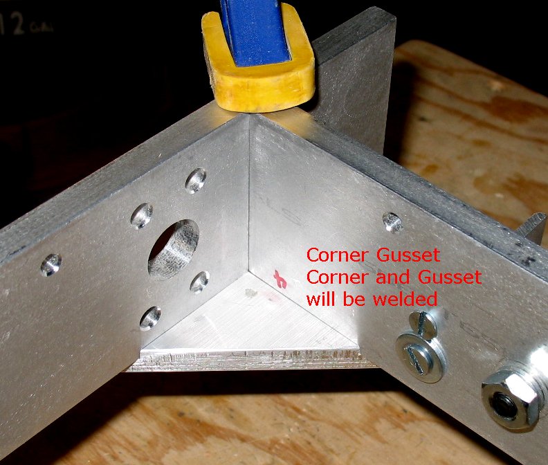 |
| Corner Gussets | Gusset clamped in place |
| - | |
| Click on the images to see a larger image | |
 |
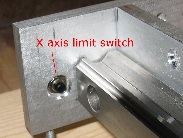 |
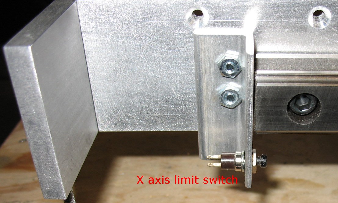
| X axis Limit switch - loosely bolted in place for now | X axis limit switch |
| - | |
Enter My Tube Amp Parts Store Here
Mobile users Enter My Tube Amp Parts Store Here
The Tube amp Library of information
Click the link above for Tube amp info, Schematics, Board building information, Projects, Mods, Transformer diagrams, Photo's, Sound clips.
There are hundreds of pages of Tube amp information on my library page.
Please visit my Tube Amplifier Forum
Here's the place you can go to ask tube amplifier questions.
You will find a large community of friendly amp builders at the link above.
Check the huge library of Schematics here
Design your own custom Turret Board or Eyelet board
DIY Layout Creator file analyzer program
DIY Layout Creator file library
Sound clips and tunes of all types
How to email me
|
MEMBER OF PROJECT HONEY POT Spam Harvester Protection Network provided by Unspam |