
| Back to Library page | |
ReVibe build infoThis was the first ReVibe I built to test the circuit |
|
| What is a ReVibe? It is a copy of Leo Fender's 6G15 standalone reverb circuit combined with the Vibrato circuit that was used on amps like the Vibrasonic and 6G12 Concert. This page has info on how these two circuits are combined This page has info on my rack ReVibe |
|
|
Note that Hoffman boards are not assembled by looking at my builds. I do test builds first and change the designs based on those builds. You assemble Hoffman boards using the documents listed below. The Layout Diagram, Schematic and BOM for this board are on this page |
|
| Click on the image below to see a larger image | |
 |
|
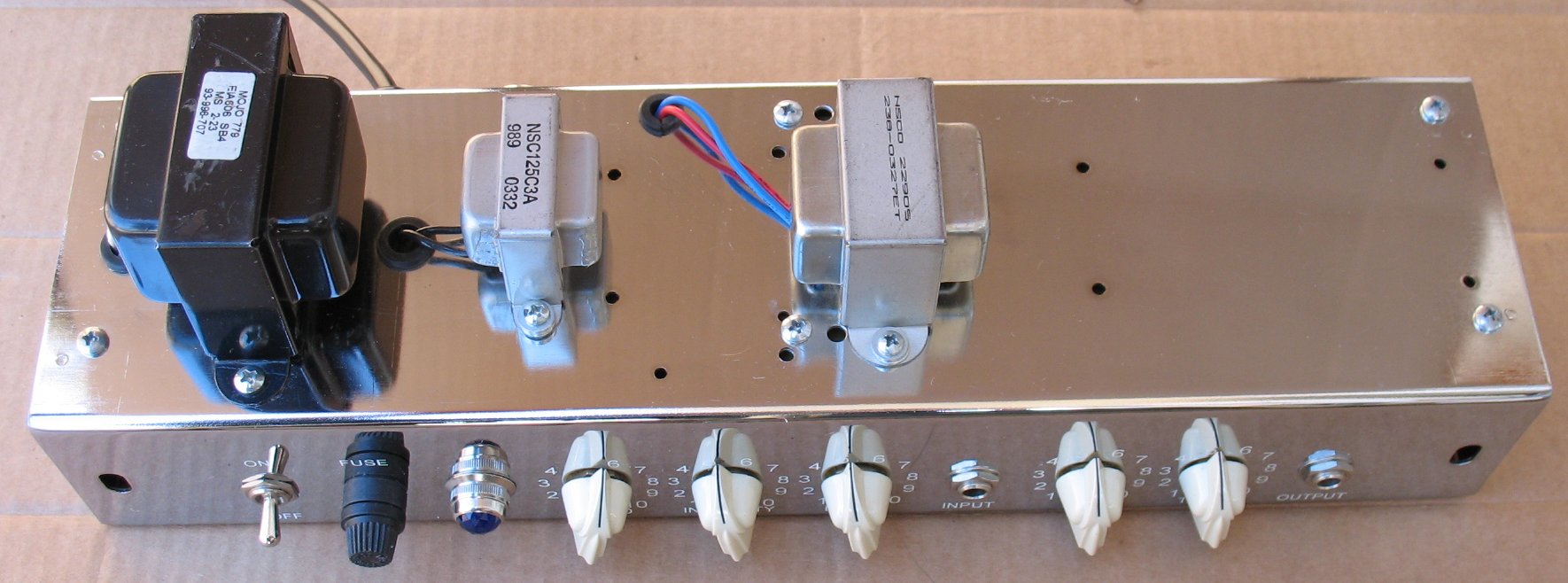
| Top and Back The 3 transformers are mounted on the back of the chassis. |
|
| Click on the image below to see a larger image | |
 |
|
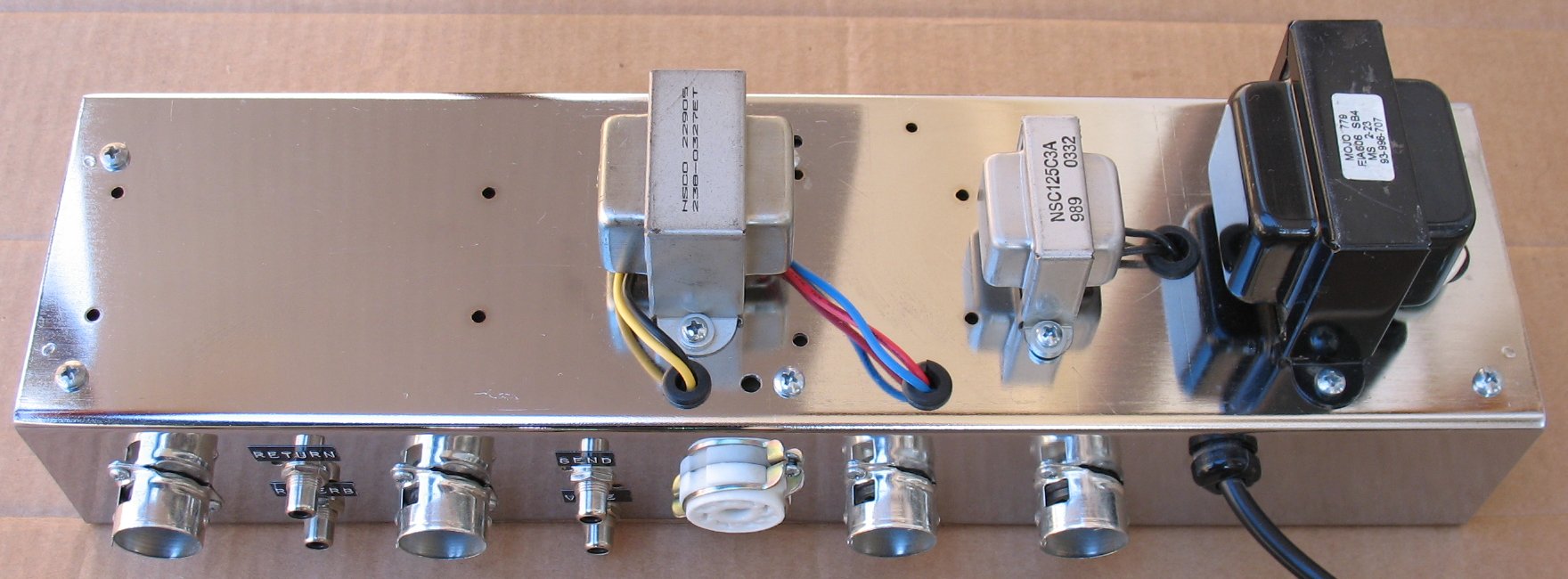
| Back and Bottom |
|
| Click on the image below to see a larger image | |
 |
|
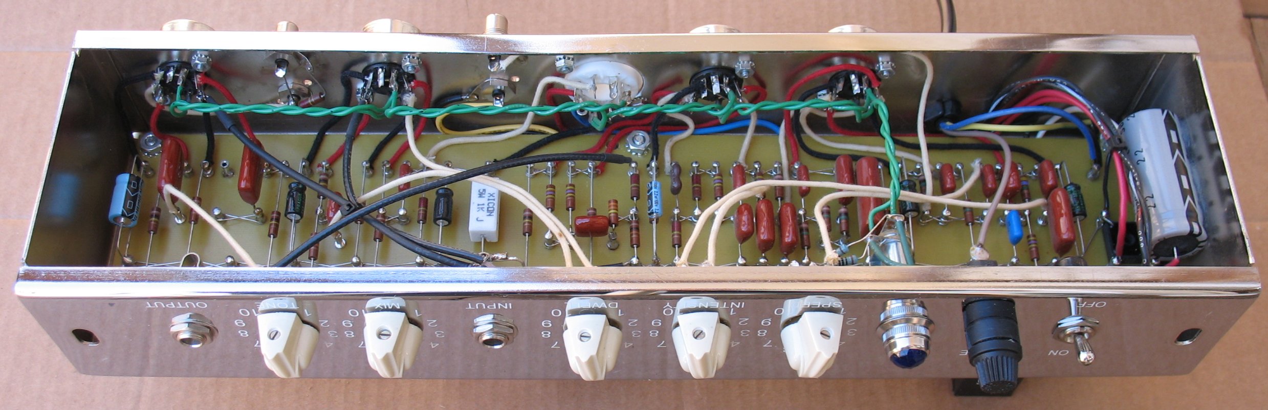
| Top and inside |
|
| Click on the image below to see a larger image | |
 |
|
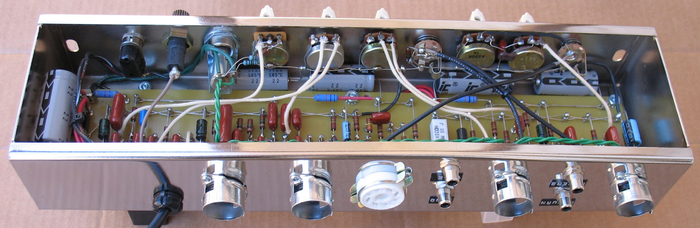
| Bottom and inside |
|
| Click on the image below to see a larger image | |
 |
|
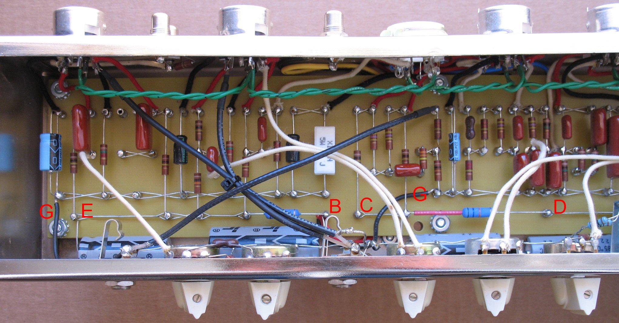
| G = Ground wires from board to pot buss wire. A, B, C, D and E are all the Filter cap stages. |
|
| Click on the image below to see a larger image | |
 |
|
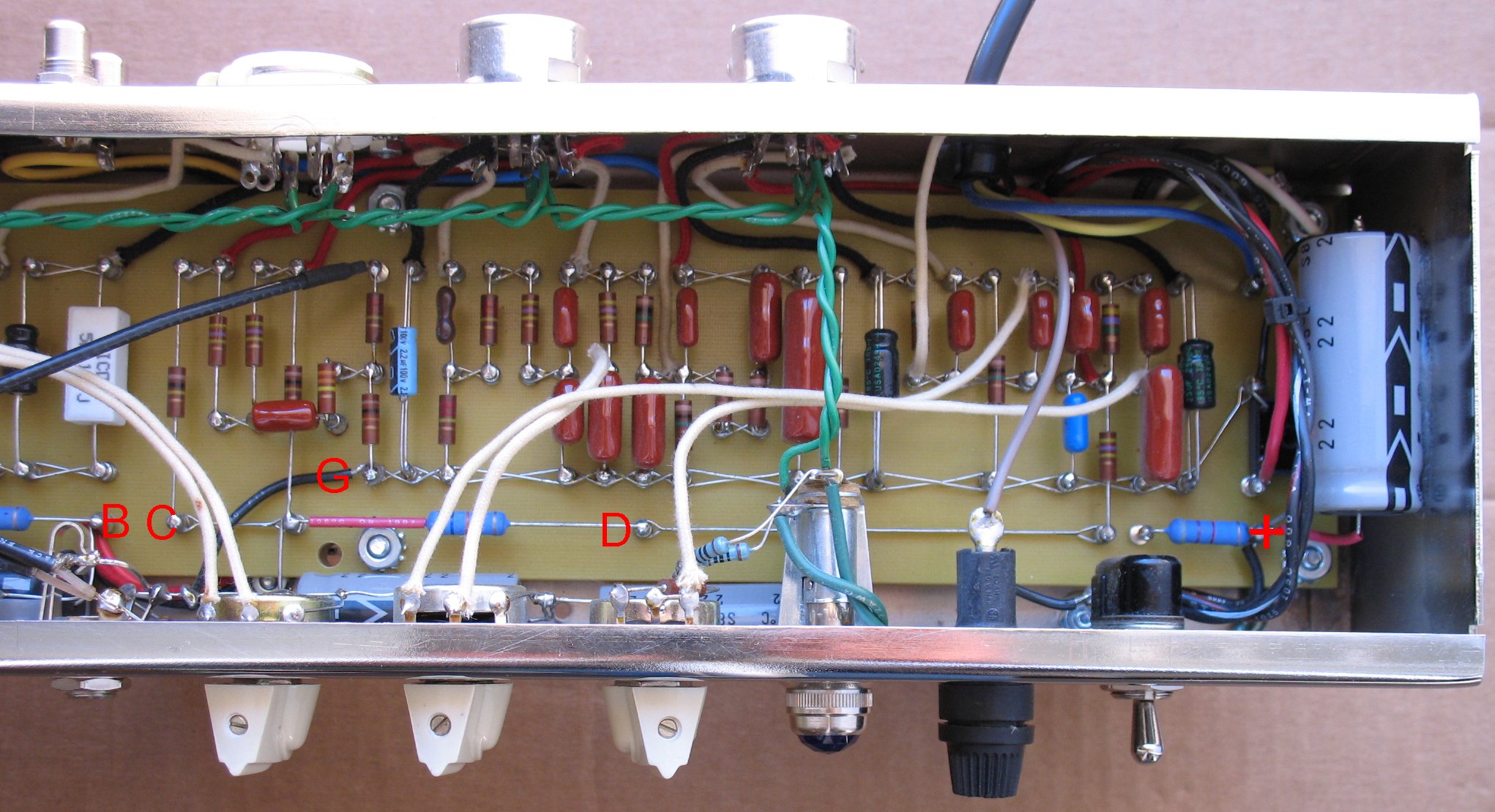
| D is a Filter cap stage. The connection lug for stage D is under the lamp assembly in this photo. + is the Main filter cap that is connected directly to the Positive terminal of the bridge rectifier. The negative of this filter cap is connected to the bridge rectifier negative terminal. The main filter cap is glued to the end of the chassis using clear silicon. I would have put this cap along the front edge under the pots if there was room, but there wasn't. I chose to put all of the filter caps inside the ReVibe instead of making a filter cap board and placing them all in a cap can on the back of the chassis. Either way will work fine. You save a bunch of labor and some parts by putting them all inside the unit. If you wanted to use another brand of caps that were larger in size than the Illinois brand, you would probably have to use a cap can and build a cap board. R1 and R2 are the 100 ohm Heater circuit artificial center tap resistors. (See Schematic on library page) They are soldered directly to the lamp terminals and then soldered to ground on the back of the Vibrato Speed pot. The green heater wires go from the power transformer, directly to the lamp assembly. The heater wires then leave the lamp and go to V5. From V5, the heaters are just run in a twisted pair from V5 down to V1. You can see the green heater wires in some of the other photo's. |
|
| - | |
| ReVibe notes: The library page has links for the ReVibe schematic, parts list and layout diagram. Refer to the layout diagram to follow the notes below. This info mostly pertains to using the chassis I used and may be different for other chassis. PT1 is a lug that is used to connect the power cord neutral wire (white) to the power transformer neutral (Usually white). PT2 is a lug that can be used to terminate power transformer wires that are not being used, or you can just heat shrink them and tuck them away. A, B, C, D and + are filter cap attachment points. See the ReVibe schematic for power transformer and filter cap hookups. If you intend on mounting your filter caps inside the chassis as I have done, you will need to mount the circuit board on 1/4 inch standoffs and very close to the tube sockets. This will give you more room under the pots to mount the caps. The 47/500v and 100/450v caps barely fit under the pots. I doubt that Sprague's will fit under the pots. You would have to build a filter cap can board and mount the caps on the rear of the chassis if you used physically larger filter caps. It was not necessary to bolt the bridge down to the circuit board. The bridge has four lugs surrounding it and once all four bridge wires are soldered to the lugs, the bridge will not move. The bridge wires are soldered to the lugs and the lugs are used to make the connections. You will have to decide where the two center circuit board mounting holes should go at the same time that you decide where you intend to bolt down the 022905 output tranny. Both sets of holes are in the same general area so some planning is needed. I bolted the green power cord ground wire to the circuit board mounting screw in the far right hand corner of the chassis. (pots facing toward you.) Even though a 3 wire power cord is specified, you will probably have to lift the power cord ground with a wall adapter. If you do not, you may end up with a ground loop since the guitar cord that goes from the ReVibe output jack to your amp already connects both chassis grounds. Update: I suggest you do not bolt down the green power cord wire to the chassis if your amp already has a good power cord chassis ground. Just terminate the green power cord wire on a board lug or use some heat shrink |
|
Enter My Tube Amp Parts Store Here
Mobile users Enter My Tube Amp Parts Store Here
The Tube amp Library of information
Click the link above for Tube amp info, Schematics, Board building information, Projects, Mods, Transformer diagrams, Photo's, Sound clips.
There are hundreds of pages of Tube amp information on my library page.
Please visit my Tube Amplifier Forum
Here's the place you can go to ask tube amplifier questions.
You will find a large community of friendly amp builders at the link above.
Check the huge library of Schematics here
Design your own custom Turret Board or Eyelet board
DIY Layout Creator file analyzer program
DIY Layout Creator file library
Sound clips and tunes of all types
How to email me
|
MEMBER OF PROJECT HONEY POT Spam Harvester Protection Network provided by Unspam |