Welcome To the Hoffman Amplifiers Forum

June 09, 2026, 07:20:28 pm
guest image
Welcome, Guest. Please login or register.
-User Name
-Password


Recent Posts

Pages: 1 2 3 [4] 5 6 7 8 9 10
31
Tube Amp Building - Tweaks - Repairs / Re: First amp build
« Last post by Mongrel714 on June 07, 2026, 09:50:24 pm »
Bias switching off with standby, does that mean the tubes are un biased when the standby is on? What effect does this have?
32
Tube Amp Building - Tweaks - Repairs / Re: First amp build
« Last post by Rontone on June 07, 2026, 05:22:53 pm »
I'm not crazy about the bias power supply switching off with the Standby switch.

Yeah, and the fusing on the Secondary HT can be better, have a look at some standby and fusing ideas here:-

https://www.valvewizard.co.uk/standby.html

https://www.valvewizard.co.uk/fuses.html
33
Tube Amp Building - Tweaks - Repairs / Re: First amp build
« Last post by Mongrel714 on June 07, 2026, 03:51:17 pm »
Thanks for the input JPK, I have totally shelved that mess, I have a new chassis built and starting to assemble, Taking my time with it, Wanting this to be closer to JCM 800 2204 style, please keep the comments and help coming, I need it!

34
AmpTools/Tech Tips / Re: Heathkit T3 signal tracer
« Last post by acheld on June 07, 2026, 02:44:18 pm »
I have no experience with this unit (which sounds like a very cool piece!), but I have purchased several amateur built Heathkit units over the years.  What I've found is that the folks who put these together modded them or made errors of various proportion.

So, my approach now is to carefully strip these apart, and then follow the manual to put them back together.  Very relaxing!  Not only are the assembly instructions good, but the test and calibration methods are very well described and easy to do.  And you normally end up with a good piece of equipment.   What could go wrong!
35
Can anyone reveal the ways the various values of mixing resistors behave in the circuit? This early Traynor had 100K ones, but I substituted 270K ones ... Maybe I'll use 220K like on a Fender AB763

The 5E3 Deluxe is a special case, and you are asking about "general use."  I will pretend we are talking about any amp other than a 5E3 Deluxe.

You look at a mixing resistor and think "100kΩ" or "220kΩ" or "470kΩ" but you should not think that.  Most of the time there are "2 resistors" because "2 signals are being mixed" and the signal-source sees those 2 resistors in-series.

   - If you have 220kΩ mixing resistors, the signal goes through one resistor, goes through the 2nd 220kΩ resistor, often sees a coupling cap, and a resistor-to-filter-cap (perhaps a "100kΩ" plate load resistor).

   - The signal therefore sees a total "resistance to ground" of 220kΩ + 220kΩ + 100kΩ (plate load) = 540kΩ.  This is a load impedance for the previous stage.

   - Higher mixing resistance ---> higher load impedance ---> somewhat higher gain for the preceding stage ---> BUT!! can create more noise.

   - Lower mixing resistance ---> less noise potential ---> BUT!! smaller load impedance ---> somewhat lower gain for the preceding stage.


The tradeoff is we want "as high as we can get away with" to "minimize gain-reduction due to loading" while also "not so big as to create excessive hiss."


Mixing resistors are typically equal-value so that 2 mixed signals are each reduced to about-half-original-strength, and the output signal is an equal-blend of the input-signals.

   - Sometimes you don't want "equal-blend" of the input signals, as in a Fender Reverb circuit.

   - Fender used a mixing network that greatly-reduced the Dry Signal, and barely-reduced the Reverb Signal because the Reverb Signal was much weaker.  The unequal-mixing was necessary to get the two signals to a proper relative balance (the mixing network is one of several places a tech could modify the relative strength of Dry and Reverb in those amps).


Can anyone reveal the ways the various values of mixing resistors behave in the circuit? This early Traynor had 100K ones, but I substituted 270K ones ... put a bunch of Marshall values into it ...

Traynor had 100kΩ at the output of Volume pots.

I am too young to have ever had 3 and 4 instruments plugged into a single tube amplifier.  There are members here who may have had the experience of several players using a single amp back in the early days when money was tight.

   - If your buddy turns down his Volume control, you don't want your guitar to get quieter, do you?

   - Mixing resistors coming out of Volume control wiper seek to prevent one Volume control setting from altering the loudness of another channel.  So they "isolate the effect of one Volume control" from another.

   - Traynor's Volume controls were 500kΩ, and they were linear-taper.
   - 100kΩ + 100kΩ = 200kΩ, which is 40% of the max-resistance of the "other-channel" Volume control.  That's probably high enough that anything above "all the way down" on the other-channel has little effect on your-channel's Loudness.


Notice that Fender used 220kΩ (or sometimes maybe 270kΩ) with 1MΩ pots ---> 220kΩ + 220kΩ is 44% of 1MΩ ---> similar ratio.  Once again the goal is "high enough resistance to do the job, but not any higher."

Others point out "filtering" and many locations will have high-frequency roll-off if the series-resistance gets too high due to capacitances-to-ground and/or Miller Capacitance at a tube-input.
36
AmpTools/Tech Tips / Re: Heathkit T3 signal tracer
« Last post by HotBluePlates on June 07, 2026, 12:22:15 pm »
... What’s up here. I mean the magic eye is an AC driven stage, so I wouldn’t think ... polarity would matter. ...

Electrons cannot flow from Plate to Cathode.
Tube (magic-eye or otherwise) passes no current unless electrons "boil out" of a hot cathode and get pulled to a Positive-Plate (with a few non-relevant exceptions).

We cannot reverse current-direction through a vacuum tube, so think of them first as "diodes" with one-way current.
We only get "AC" when our one-way current gets bigger/smaller, and we strip off the large DC part of that changing-current with a blocking capacitor.

So from an initial thought, polarity always matters.

When I plug the unit into mains, the optical magic eye indicator only responds with the heathkit T3 is antiphase plugged in.
(Dmm in AC, across the T3 and a grounded device, shows mains potential across units)

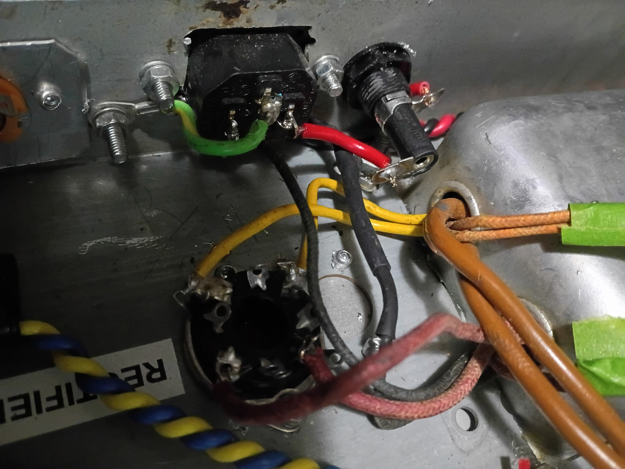
I wonder if you removed the "death cap" (0.05µF to ground at the PowerSwitch on the schematic).

That cap strips off RF noise riding on the line, and puts XC = 1 / (2 x π x 0.05µ x 120Hz) = ~26.5kΩ between one side of the line and Chassis.

If you added a 3-prong cord and removed that cap the "other side" of the line should theoretically be bonded to chassis/Ground at the service panel (is it?  :dontknow:).

I am coming around to the nothing that "Death Cap" is a bogus-warning in the era of plastic caps (of the mid-60s blue "Ajax" caps in Fender or later), but that paper-dielectric caps and a few very early plastic caps cannot be trusted.  Modern Class Y caps may be "metallized paper" but they are rated for safe-failure when connected from Line-to-Ground (they are guaranteed to fail-open, and never fail-short).

So that's one aspect that might be relevant to your observation.  The other is:
The unit is a kit build ... 2 prong similar blade power cable.

When I plug the unit into mains, the optical magic eye indicator only responds with the heathkit T3 is antiphase plugged in.
(Dmm in AC, across the T3 and a grounded device, shows mains potential across units)

So with mains polarity aligned, T3 doesn’t illustrate readings optically ...

... I wouldn’t think mains ac polarity would matter.

Should I just swap PT primary for the ... transformer? ...

I hadn't read the manual, but I see there is a "3rd Setting" that disconnects the Audio Input from the 1629, and instead connects one side of a PT winding (whose other-side is connected to Diodes on the 12C8.  At a glance, this appears to be a "diode detector" for Line Voltage, where the resistors and 0.05µF cap give a slowly-changing DC Voltage that is proportional to the Line Voltage (governed by the Pot; maybe a "Wattage" Pot?).  This DC Voltage is applied to the 1629's triode-grid, so once again, polarity matters.


But I see a bunch of primary wires on the power transformer, and they're all "Black"... If you still have the 2-prong cord, you would just flip the cord over to make the magic eye work.  If it worked for audio, but not for what I assume is "Watts" then you would swap Black wires on the second-primary to get that feature working.

__________________________________________

When I plug the unit into mains, the optical magic eye indicator only responds with the heathkit T3 is antiphase plugged in.
(Dmm in AC, across the T3 and a grounded device, shows mains potential across units)

Now that I think for a second... vintage test gear never assumed the chassis was "0v relative to earth" and usually did not want the "test gear chassis" to be connected to the "device under test chassis."  Inputs were typically floated off the chassis, and yes, there could be significant (even dangerous) voltages between one item connected to Line Voltage and another item connected to Line Voltage.  (Reminds me also of the use of "Line Isolation Transformers" that intentionally divorce a tested piece of gear from other line-connected devices, so voltage-differentials like this can be squashed while keeping a 3rd-prong connection to Ground at the service panel).


You can try swapping PT primary-wires, but there's a chance this is "just the way it is" (I haven't really thought enough about it to know whether the chassis voltage-differential would go away).
37
Sound clips / Re: Midnight Surf
« Last post by EL34 on June 07, 2026, 11:06:24 am »
Such nice dripping wet reverb tone. Awesome surf music.

Thanks
38
Sound clips / Re: Midnight Surf
« Last post by JPK on June 07, 2026, 11:02:46 am »
Such nice dripping wet reverb tone. Awesome surf music.
39
Other Topics / Re: Meme of the day
« Last post by shooter on June 07, 2026, 09:20:19 am »
...
40
Tube Amp Building - Tweaks - Repairs / Re: First amp build
« Last post by JPK on June 07, 2026, 08:51:59 am »
I'm not crazy about the bias power supply switching off with the Standby switch. Should be powered in Standby like the heaters. There are better layouts out there as was mentioned. I attached the last 50 watt I assembled. Bias power is not switched off in Standby.

acheld and Dogburn, and sluckey, Thank you for the reply's!
What I was hoping to build is a JCM 800 type 50w circuit, I don't know yet if the transformer is the proper voltage, The circuit I'm looking at is posted below,
I have been debating on moving the output transformer, so now Ill do that, and the signal wire advice will be taken acheld!
and sluckey, thank you for noticing that, I will correct that, mentioning the rectifier socket, using the diagram below, should I use the tube rectifier, or go with a Solid state rectifier here? I have already ordered a components kit with all the smaller resisters and caps, diodes, so whichever I should use would be fine with me!
 The turret board I'm using is 10" long so its a little cramped but should work, will there be a problem running anything under it given enough clearance?
I installed the proper fuse holder next to the power inlet, I have another on the way for the H.T. Thanks again guys!
Pics!


Pages: 1 2 3 [4] 5 6 7 8 9 10

Choose a link from the
Hoffman Amplifiers parts catalog
Mobile Device
Catalog Link
Yard Sale
Discontinued
Misc. Hardware
What's New Board Building
 Parts
Amp trim
Handles
Lamps
Diodes
Hoffman Turret
 Boards
Channel
Switching
Resistors Fender Eyelet
 Boards
Screws/Nuts
Washers
Jacks/Plugs
Connectors
Misc Eyelet
Boards
Tools
Capacitors Custom Boards
Tubes
Valves
Pots
Knobs
Fuses/Cords Chassis
Tube
Sockets
Switches Wire
Cable


Handy Links
Tube Amp Library
Tube Amp
Schematics library
Design a custom Eyelet or
Turret Board
DIY Layout Creator
File analyzer program
DIY Layout Creator
File library
Transformer Wiring
Diagrams
Hoffmanamps
Facebook page
Hoffman Amplifiers
Discount Program


password